
Lecture
Planar Straight-Line Graph ( PSLG ) — is a term used in computational geometry for an embedding of a planar graph in the plane such that its edges become straight-line segments. Fáry's theorem (1948) states that every planar graph has an embedding of this type.
A planar graph laid out in the plane is customarily called plane. A planar embedding of a planar graph G=(V,E) — is a mapping of each vertex from V to a point in the plane, and each edge from E to a simple line connecting the pair of images of the endpoints of that edge, such that the images of the edges intersect only at their endpoints. It is well known that any planar graph can be laid out in the plane so that all edges are mapped to straight-line segments.
In computational geometry, a PSLG is often called a planar subdivision, with the assumption or assertion that the subdivision is polygonal. A maximal planar subdivision is one to which it is impossible to add a single edge joining two vertices without violating planarity.
A PSLG with no vertices of degree 1 defines a subdivision of the plane into polygonal regions, and vice versa. The absence of vertices of degree 1 simplifies the description of many algorithms, but this is not essential.
A PSLG can serve as a representation of various kinds of maps. For example, a geographic map in a geographic information system.
A special case of a PSLG is a triangulation: triangulation of a polygon, triangulation of a set of points. A point-set triangulation is a maximal PSLG in the sense that it is impossible to add straight-line edges to it while keeping the graph planar. Triangulations have numerous applications in various fields.
A PSLG can be regarded as a special kind of Euclidean graph . However, in discussions related to Euclidean graphs, the main interest lies in their metric properties, that is, the distances between vertices, whereas for a PSLG the main interest is related to topological properties. For some graphs, such as the Delaunay triangulation, both metric and topological properties are of considerable importance.
A doubly connected edge list is especially convenient for representing a PSLG. Let a graph G=(V,E) V={v1,v2...vn} and E={e1,e2...en} be given. The main component of the DCEL for a planar graph is the edge node. There is a one-to-one correspondence between the edges of the graph and the edge nodes of the DCEL, i.e., each edge is represented exactly once in the DCEL. The DCEL edge node corresponding to a graph edge, for example, ek={v1,v2} has 4 fields (V1,V2,F1,F2 ) and 2 pointers (P1,P2 ). The field V1 contains the start of the edge, and the field V2 contains its end (in this way, an initially undirected edge acquires a conditional orientation). The fields F1 and F2 contain the names of the faces lying to the left and to the right of the directed edge (v1,v2 ). The pointer P1 (respectively P2 ) specifies the edge node containing the first edge encountered after the edge (v1,v2 ), when turning from it counterclockwise around v1 (respectively v2 ).
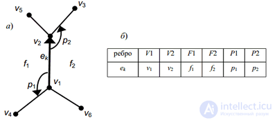
Representation of a plane graph using a DCEL
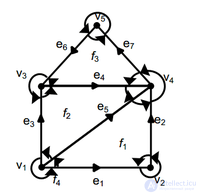
A plane graph whose edges have been given an arbitrary orientation in order to represent it using a DCEL. The arrows around the vertices correspond to the pointers (P1, P2)
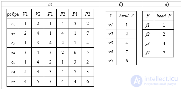
(a) DCEL, (b) entries by vertex head_V [1..n], and (c) entries by face head_F[1..l]
DCEL — Doubly Connected Edge List.
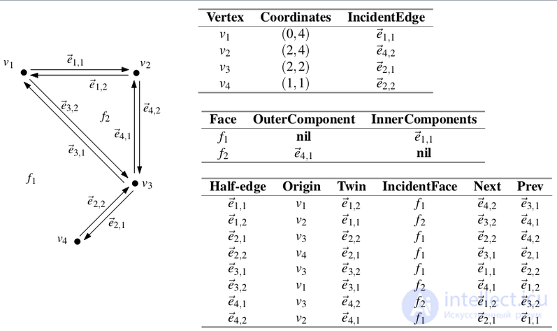
Towards the second description
A DCEL consists of 3 components:
struct vertex {
    x, y;
    half_edge *rep;  /* rep->origin == this */
};
struct face {
    half_edge *out;
    list in;
};
struct half_edge {
    half_edge *prev;     /* prev->next == this */
    half_edge *next;     /* next->prev == this */
    half_edge *twin;     /* twin->twin == this */
    vertex *origin;      /* twin->next->origin == origin &&
                            prev->twin->origin == origin */
    face *incident_face; /* prev->incident_face == incident_face &&
                            next->incident_face == incident_face */
};
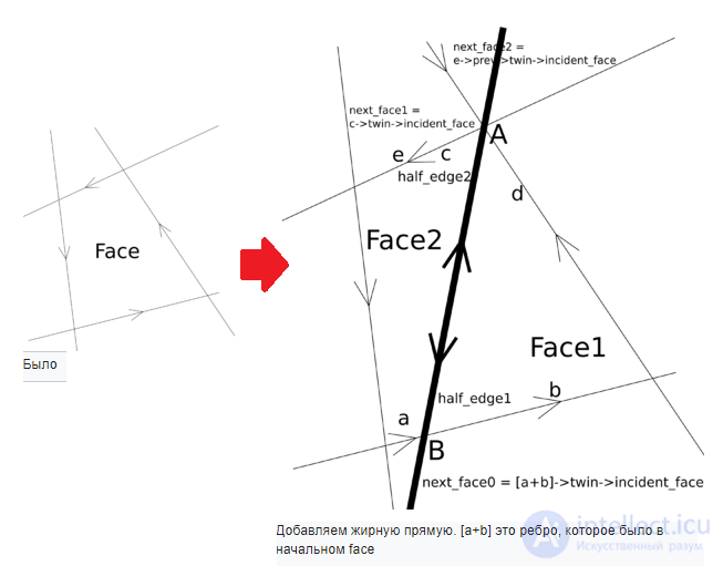
the corresponding chapter from de Berg needs to be rewritten here.
We have a set of lines. We want to represent this set as a DCEL.
We will add the lines one at a time. Initially we have a single face that represents the entire plane. The algorithm will be as follows:
Here are the references that must not be forgotten:
half_edge1->origin = A;
half_edge2->origin = B;

half_edge1->twin = half_edge2;
half_edge2->twin = half_edge1;
half_edge1->incident_face = face1;
half_edge2->incident_face = face2;

half_edge1->next = b;
b->prev = half_edge1;
half_edge1->prev = d;
d->next = half_edge1;

half_edge2->next = c;
c->prev = half_edge2;
half_edge2->prev = a;
a->next = half_edge2;

Comments