
Lecture
Hydraulic machines are machines that
impart mechanical energy to the fluid flowing through them
(pumps), or receive part of the energy from the fluid and transfer it to a working
member for useful application (hydraulic motors).
Pumps and hydraulic motors are also used in hydraulic transmissions,
whose purpose is to transmit mechanical energy from the
engine to the actuating member, as well as to convert the type and
speed of the latter's motion by means of a fluid.
Compared with mechanical transmissions (couplings,
gearboxes, reduction gears, etc.), hydraulic transmissions have the following advantages.
1. Smoothness of operation.
2. The possibility of stepless speed control.
3. Lower dependence of the torque on the output shaft on the load
applied to the actuating member.
4. The ability to transmit large amounts of power.
5. Small overall dimensions.
6. High reliability.
These advantages have led to the widespread use of
hydraulic transmissions, despite their somewhat lower efficiency compared with mechanical
transmissions.
Modern engineering employs a large number
of machine types. The most widespread for water supply to the
population are vane pumps. The working member of a vane
machine is a rotating impeller fitted with blades.
Vane pumps are divided into centrifugal and axial types.
In a centrifugal vane pump the fluid, under the action of
centrifugal forces, moves through the impeller from the center to the
periphery.
Figure 7.1 shows the simplest diagram of a centrifugal pump.
The pump's flow section consists of three main elements – the inlet 1,
the impeller 2, and the outlet 3. Through the inlet, fluid is fed into the impeller
from the supply pipeline. Impeller 2 transfers to the fluid
energy from the drive motor. The impeller consists of two discs
a and b, between which are located blades c, curved in the direction
opposite to the direction of rotation of the wheel. The fluid moves
through the impeller from its central part toward the periphery. Through the outlet, the fluid
is discharged from the impeller to the discharge branch pipe or, in
multistage pumps, to the next impeller.
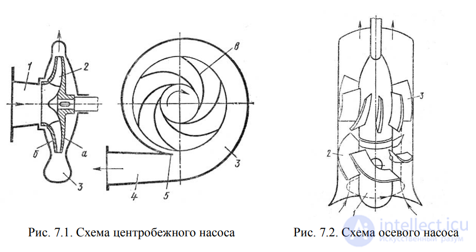
Fig. 7.1. Diagram of a centrifugal pump Fig. 7.2. Diagram of an axial pump
In an axial vane pump the fluid moves mainly
along the axis of rotation of the impeller (Fig. 7.2). The impeller of an axial
pump resembles a ship's propeller. It consists of a hub 1, on which
several blades 2 are mounted. The pump's outlet is served by an axial
guide vane assembly 3, by means of which the swirl of the fluid is eliminated, and its kinetic energy is converted into pressure energy.
Axial pumps are used with large flow rates and low pressures.
Axial pumps can be fixed-blade, in which
the position of the impeller blades does not change, or variable-pitch, in which
the position of the impeller can be adjusted.
Piston pumps belong to the class of positive-displacement pumps, in which
the movement of the fluid is accomplished by displacing it from
fixed working chambers by means of displacers. The working chamber of a positive-displacement
pump is a bounded space that alternately communicates
with the pump's inlet and outlet. A displacer is the working member of the pump
that performs the displacement of fluid from the working chambers
(plunger, piston, diaphragm).
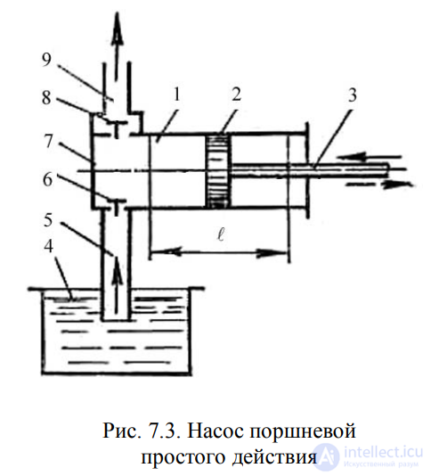
Fig. 7.3. Single-acting piston pump
Piston pumps are classified according to the following features:
1) by type of displacer: plunger, piston, and diaphragm pumps;
2) by the character of motion of the drive link: reciprocating
motion of the drive link; rotary motion of the drive link
(crank-type and cam-type pumps);
3) by the number of discharge and suction cycles per double stroke:
single-acting; double-acting.
4) by number of pistons: single-piston; two-piston;
multi-piston.
Single-acting pump. The diagram of a single-acting pump
is shown in Fig. 7.3. Piston 2 is connected to the crank-and-connecting-rod
mechanism through rod 3, as a result of which it performs reciprocating
motion in cylinder 1. During its stroke
to the right, the piston creates a vacuum in the
working chamber, causing
suction valve 6
to lift, and fluid from
supply reservoir 4
flows through the suction pipeline 5
into working chamber 7.
On the return stroke of the piston (to the left)
the suction valve closes,
while discharge valve 8
opens, and the fluid
is discharged into the discharge
pipeline 9.
Since each revolution
of the motor corresponds to two strokes
of the piston, of which only one corresponds to discharge,
the theoretical output per second will be
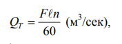 , (7.1)
where F – piston area, m2;
l - piston stroke, m;
n – motor rotational speed, rpm.
To increase the output of piston pumps, they are often
made as duplex, triplex, and so on. The pistons of such pumps
are driven from a single crankshaft with offset cranks.
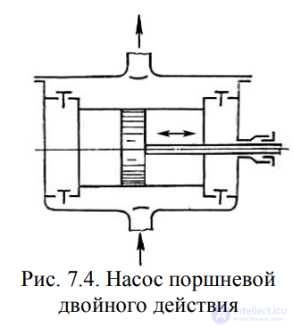
Fig. 7.4. Double-acting piston pump
The actual output of pump Q is less than the
theoretical output, since leaks occur due to
untimely closing of the valves, imperfect sealing in the valves and
in the piston and rod seals, as well as incomplete filling of the working
chamber.
The ratio of the actual flow rate Q to the theoretical flow rate QT is called
the volumetric efficiency of a piston pump:
 . (7.2)
Volumetric efficiency is the main economic indicator
characterizing the operation of the pump.
Double-acting pump. A more uniform and increased delivery
of fluid, compared with a single-acting pump, can be
achieved with a double-acting pump
(Fig. 7.4), in which each stroke of the piston
corresponds simultaneously to suction and discharge
processes. These pumps
are made horizontal and
vertical, with the latter being the most
compact. The theoretical output
of a double-acting pump will be
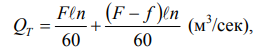 , (7.3)
where f – rod cross-sectional area, m2
.
Differential pump. In a differential pump (Fig. 7.5)
piston 4 moves within a smoothly finished cylinder 5. The seal of the
piston is provided by gland 3 (option I) or a small clearance (option II) with
the cylinder wall. The pump has two valves: a suction valve 7 and
a discharge valve 6, as well as an auxiliary chamber 1. Suction
occurs during one stroke of the piston, while discharge occurs during both strokes. Thus, on the
piston's leftward stroke, a volume of fluid equal to (F - f) is displaced from the auxiliary chamber
into discharge pipeline
2; on the piston's rightward stroke a volume of fluid equal to f is displaced from the main chamber. Thus,
over both strokes of the piston, a volume of fluid equal to
 (7.4)
(7.4)
will be delivered into the discharge pipeline,
i.e., the same amount as delivered by a single-acting pump. The only difference
is that this quantity of fluid is delivered over both strokes of the piston,
and consequently the delivery is more uniform. In this case
the output is determined by formula (7.1)
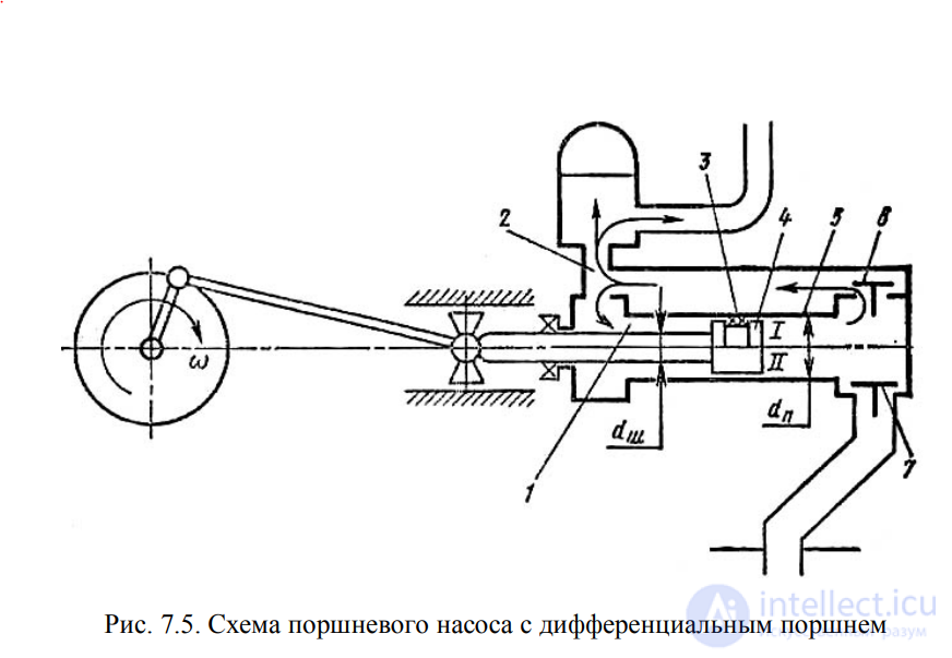
Fig. 7.5. Diagram of a piston pump with a differential piston
7.3. Indicator Diagram of Piston Pumps
The working cycle of a piston pump can be graphically depicted on
paper by a special instrument – an indicator. The graph of pressure change
in the cylinder over one complete revolution of the crank is called the
indicator diagram. Figure 7.6 shows such a diagram for a
single-acting pump.
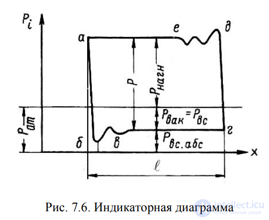
Fig. 7.6. Indicator diagram
When the piston moves from left to right (see Fig. 7.3) (the suction
process), the pressure in the pump cylinder drops sharply to the suction
pressure Pvs along line ab. Due to the flexibility of the cylinder walls and
the compressibility of the fluid, line ab is not vertical but slightly inclined and
then transitions into wavy line bc. Further along the suction line,
a constant pressure is maintained and line cd remains practically
horizontal throughout the entire suction stroke. During the return
motion of the piston (the discharge stroke), the pressure in the cylinder rises from Pvs
to discharge pressure Pd along straight line de, whose slope to the left of the
vertical is explained by the same causes as for line ab.
The onset of fluid compression is accompanied by pressure fluctuations in the
cylinder (line ef). Subsequently the pressure Pd remains constant throughout
the entire discharge stroke (line fa). On the next working
cycle this graph will repeat.
Malfunctions occurring in the hydraulic part of a piston
pump alter the shape of the indicator diagram. By analyzing
various indicator diagrams with one anomaly or another,
one can determine the pump's malfunction without error.
The power balance in a pump can be clearly represented in the form of the diagram shown in Fig. 7.7.
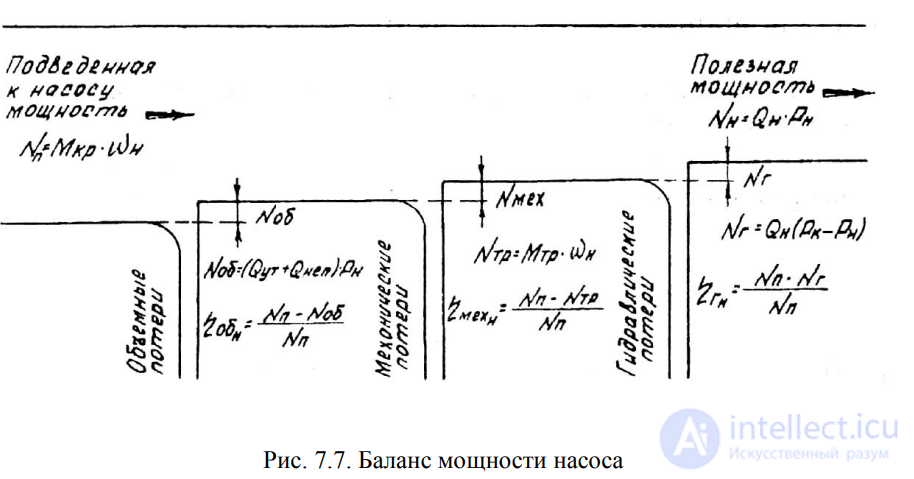
Fig. 7.7. Pump power balance
The power supplied to the pump shaft is called the
input power. It is equal to the product of the torque on the shaft and its
angular velocity
 (7.5)
(7.5)
The power that we obtain from the pump in the form of a flow of fluid
under pressure is called the useful power of the pump (hereinafter
simply the power)
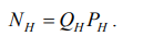 . (7.6)
The ratio of the pump power to the input power is called
the overall efficiency of the pump
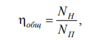 , (7.7)
and the difference 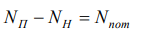 is called the power losses in the pump.
Power losses in a pump are divided into volumetric, mechanical, and hydraulic losses.
Power losses due to internal leakage and incomplete filling of the pump chambers
 . (7.8)
The volumetric efficiency of the pump is determined from the relation
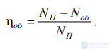 . (7.9)
For modern pumps the volumetric efficiency lies within the range of 0.92…0.96. Efficiency values are given in the pumps' technical specifications.
Mechanical efficiency characterizes the friction losses in the moving joints between the pump's parts. When contacting surfaces move relative to one another, a friction force always arises in the zone of contact,
directed opposite to the motion. This force is expended on deformation of the surface layer, plastic displacement, and on overcoming the intermolecular bonds of the contacting surfaces.
The power expended on overcoming friction forces is determined by
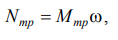 (7.10)
where Mfr – friction torque in the pump;
ω – angular velocity of the pump shaft.
The mechanical efficiency is determined from the relation
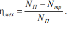 (7.11)
For modern pumps the mechanical efficiency also lies within
the range of 0.92…0.96.
Hydraulic efficiency characterizes the losses due to deformation of the flow
of the working fluid in the discharge chamber and to friction of the fluid against the walls
of the vessel. These losses are approximately an order of magnitude lower than the mechanical friction
losses and are often not taken into account in engineering calculations, or are combined
with the mechanical friction losses. In this case the combined efficiency
is called the hydromechanical efficiency.
The power expended on hydraulic losses is determined by
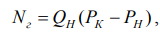 , (7.12)
where Pk – pressure in the pump's discharge chamber;
Pn – pressure in the discharge hydraulic line at the pump outlet.
The hydraulic efficiency is determined from the relation
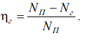 . (7.13)
The overall efficiency of the pump is equal to the product of the volumetric,
hydraulic, and mechanical efficiencies
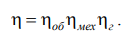 . (7.14)
Thus, the pump's power balance gives an idea of the
losses arising in the pump, its overall efficiency, and all its components.
In addition to pumps and hydraulic motors, there exist other various
hydraulic elements differing in design and purpose. Some control the flow
of the working fluid, others serve to ensure the reliable operation of
hydraulic systems, etc. The set of these devices is called a
hydraulic drive and requires separate study. All hydraulic elements have
their own conventional symbol, from which hydraulic diagrams are composed by
analogy with electrical circuit diagrams. Below are given the conventional
symbols of the main hydraulic elements.
Table 7.1 Conventional Symbols of the Main Hydraulic Elements
| Symbol | Description of the element |
 |
Non-adjustable hydraulic pump with constant flow direction |
 |
Non-adjustable hydraulic pump with reversible flow direction |
 |
Adjustable hydraulic pump |
 |
Non-adjustable hydraulic motor with constant flow direction |
 |
Non-adjustable hydraulic motor with reversible flow direction |
 |
Adjustable hydraulic motor |
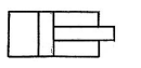 |
Piston-type hydraulic cylinder with single-sided rod |
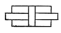 |
Piston-type hydraulic cylinder with double-sided rod |
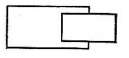 |
Plunger-type hydraulic cylinder |
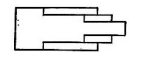 |
Telescopic hydraulic cylinder |
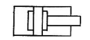 |
Hydraulic cylinder with end-of-stroke cushioning |
 |
Adjustable throttle |
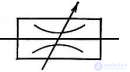 |
Regulating throttle |
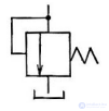 |
Pressure relief valve |
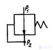 |
Pressure-reducing valve (P2 = const at P1 |
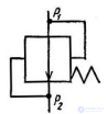 |
Pressure-differential valve (P1 P2 = const) |
 |
Check valve |
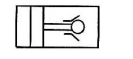 |
Hydraulic lock |
 |
Weight-loaded hydraulic accumulator |
 |
Spring-loaded hydraulic accumulator |
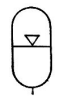 |
Pneumo-hydraulic accumulator |
 |
Filter |
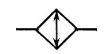 |
Heat exchanger |
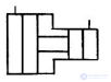 |
Hydraulic transducer |
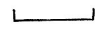 |
Hydraulic tank at atmospheric pressure |
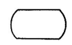 |
Hydraulic tank at above-atmospheric pressure |
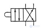 |
Four-way directional control valve, two-position, cam-operated |
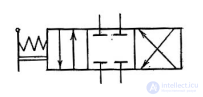 |
Four-way directional control valve, three-position, manually operated with blocked flow in the neutral position |
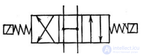 |
Four-way directional control valve, three-position, solenoid-operated with looped flow in the neutral position |
Figure 7.8 shows an example of a hydraulic diagram, composed from conventional symbols, of the boom-swing drive of a jaw loader.
The diagram consists of a tank, a non-adjustable hydraulic motor, a three-position directional control valve, two adjustable throttles with check valves connected in parallel to them, two
hydraulic cylinders, a filter, and a safety valve.

Fig. 7.8. Hydraulic diagram of the boom-swing drive
The operating principle of the hydraulic drive is as follows. From the tank
the working fluid (oil) is drawn by the pump and fed to the
directional control valve. In the neutral position of the directional control valve's spool,
with the pump running, the pressure begins to rise in the section of pipeline
between the pump and the valve; at
this point the safety valve opens and the fluid drains
back into the tank. When the spool position is changed (the lower position in the diagram),
the flow passages in the directional control valve open, and the fluid
begins to flow into the discharge cavities of the hydraulic motors (the piston-side
cavities of the hydraulic cylinders). From the rod-side cavity of the hydraulic cylinders, the oil
passes along the return line through the adjustable throttles,
the directional control valve, and, being cleaned by the filter, drains into the tank.
The speed of the forward motion of the hydraulic cylinder rods
is regulated by the throttles. Reversal of the rods' motion
is accomplished by switching the positions of the directional control valve. On
the return stroke of the rods without a load, their speed is not regulated and
depends on the flow rate of the working fluid into the rod-side cavities. In the event of an emergency
stop of the rods (e.g., an insurmountable force), the pressure in the system
rises, thereby causing the safety valve to open and
discharge the working fluid into the tank.

Comments