
Lecture
Let us consider various cases of liquid discharge from reservoirs,
tanks, and boilers through orifices and nozzles (short tubes of various
shapes) into the atmosphere or into a space filled with gas or with the same
liquid. In the course of such discharge, the reserve of potential energy
possessed by the liquid in the reservoir is converted into the
kinetic energy of a free jet.
The main question of interest in this case is
determining the discharge velocity and flow rate of the liquid for various shapes
of orifices and nozzles.
Consider a large reservoir with a liquid under pressure P0,
having a small round orifice in the wall at a sufficiently large
depth H0 below the free surface (Fig. 5.1). The liquid flows out into
an air space with pressure P1. Let the orifice have the shape
shown in Fig. 5.2, a, i.e.
made as a bore in a thin
wall without machining of the inlet edge,
or have the shape shown in
Fig. 5.2, b, i.e. made in a thick
wall, but with the inlet edge
sharpened on the outer side. The jet,
separating from the edge of the orifice,
contracts somewhat (Fig. 5.2, a).
This contraction is caused by the motion of
the liquid from various directions,
including radial
motion along the wall, toward axial
motion in the jet.
In this case, when the side
walls and the free surface do not
affect the inflow of liquid to the orifice, complete
contraction of the jet is observed, i.e. the greatest contraction, as opposed to incomplete contraction.
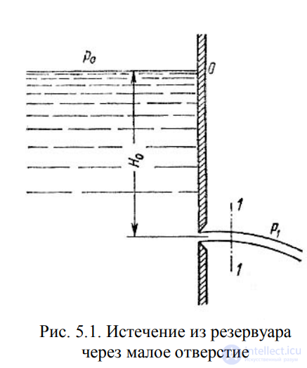
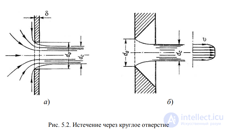
Fig. 5.2. Discharge through a round orifice
The degree of contraction is evaluated by the contraction coefficient.
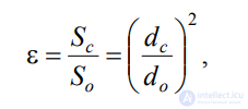 , (5.1)
where Sc and So are the cross-sectional areas of the jet and the orifice
respectively; dc and do are the diameters of the jet and the orifice respectively.
The discharge velocity of the liquid through such an orifice
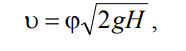 , (5.2)
where H is the liquid head, is determined as
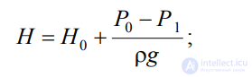
– velocity coefficient
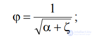 ; (5.3)
– Coriolis coefficient;
– orifice resistance coefficient.
The flow rate of the liquid is determined as the product of the actual
discharge velocity and the actual cross-sectional area:
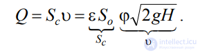 . (5.4)
The product of and is customarily denoted by the letter and called
the discharge coefficient, i.e. .
As a result we obtain the flow rate
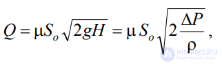 (5.5)
(5.5)
where P is the design pressure difference under whose action
the discharge occurs.
Using expression (5.5), the main problem is solved –
determining the flow rate.
The values of the contraction coefficient , the resistance coefficient , the velocity coefficient , and the
discharge coefficient for a round orifice can be determined from empirically
established relationships. Fig. 5.3 shows the relationships
of the coefficients , and as functions of the Reynolds number, calculated for
the ideal velocity
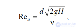
where is the kinematic viscosity.
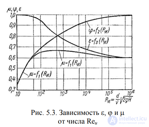
Fig. 5.3. Dependence of , and on the Reynolds number Reu
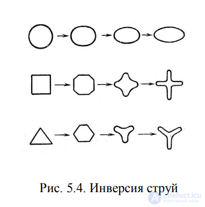
Fig. 5.4. Jet inversion
When a jet discharges into the atmosphere from a small orifice in a thin
wall, a change in the jet's shape occurs along its length, called
jet inversion (Fig. 5.4). This phenomenon is caused mainly by
the action of surface tension forces on the outflowing curvilinear
jet filaments and by varying contraction conditions around the perimeter of the orifice.
Inversion is most pronounced during discharge from non-circular
orifices.
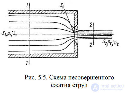
Fig. 5.5. Diagram of incomplete jet contraction
Incomplete contraction is observed when the
discharge of liquid through an orifice and the formation of the jet are
affected by the proximity of the side walls of the reservoir (Fig. 5.5).
Since the side walls
partially direct the motion of the
liquid as it approaches the
orifice, the jet at the exit from the
orifice contracts to a lesser
degree than from a reservoir
of unlimited size, as
described in Section 5.1.
For the discharge of liquids from a
cylindrical reservoir
of circular cross-section through a round
orifice located at the
center of the end wall, at large Re numbers the contraction coefficient for
an ideal liquid can be found from the formula presented by
N.E. Zhukovsky:
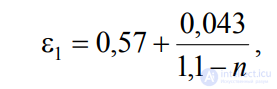 (5.6)
(5.6)
where n is the ratio of the orifice area So to the cross-sectional area of the
reservoir S1
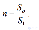
The flow rate of the liquid under incomplete contraction
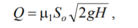 , (5.7)
where the head H must be found taking into account the velocity head in the reservoir
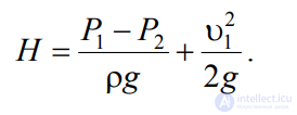 . (5.8)
It is often necessary to deal with the discharge of liquid not into the
atmosphere, but into a space filled with the same liquid (Fig. 5.6).
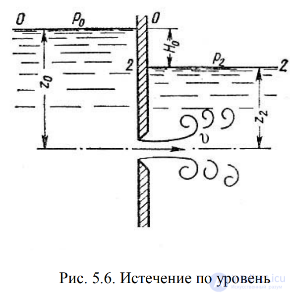
Fig. 5.6. Submerged discharge
This case is called submerged discharge, or discharge through a
submerged orifice.
In this case, all of the
kinetic energy of the jet
is lost to eddy formation, as
in a sudden expansion.
The discharge velocity at the contracted
cross-section of the jet
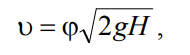 , (5.9)
where is the velocity coefficient,
determined by formula (5.3);
H is the design head,
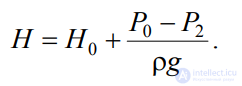 . (5.10)
The flow rate of the liquid equals
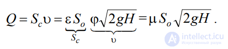 . (5.11)
Thus, we have the same design formulas as for
discharge into air (gas), except that the design head H in this case
represents the difference in hydrostatic heads on either side of the wall, i.e.
the velocity and flow rate of the liquid in this case do not depend on the height
at which the orifice is located.
The contraction and discharge coefficients for submerged discharge can
be taken the same as for discharge into an air environment.
An external cylindrical nozzle is a short tube
whose length equals several diameters, without rounding of the inlet edge
(Fig. 5.7). In practice, such a nozzle is often obtained in cases where
a bore is made in a thick wall and the inlet
edge is not machined. Discharge through such a nozzle into a gaseous medium can
occur in two regimes.
The first regime is the non-separated regime. During discharge, the jet, after
entering the nozzle, contracts approximately the same way as during discharge through an
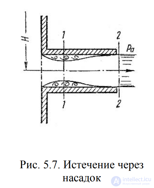
Fig. 5.7. Discharge through a nozzle
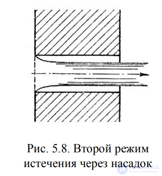
Fig. 5.8. Second regime of discharge through a nozzle
orifice in a thin wall. Then the jet gradually expands to the
size of the orifice and exits the nozzle at full cross-section (Fig. 5.7).
The discharge coefficient , which depends on the relative length of the nozzle
l/d and on the Reynolds number, is determined by the empirical formula:
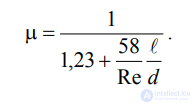 . (5.12)
Since at the exit of the nozzle the diameter of the
jet equals the diameter of the orifice, the
contraction coefficient = 1 and, consequently,
= , and the resistance coefficient = 0.5.
If we write the Bernoulli equation for the
contracted section 1-1 and the section beyond the nozzle 2-2
and transform it, we can obtain the
pressure drop inside the nozzle
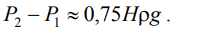 . (5.13)
At a certain critical head Hcr, the absolute pressure inside the
nozzle (section 1-1) becomes equal to zero (P1 = 0), and therefore
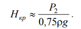 . (5.14)
Consequently, for H > Hcr the pressure P1 would have to become
negative, but since negative pressures do not occur in liquids,
the first flow regime becomes impossible. Therefore,
at H Hcr a change of the discharge
regime occurs, a transition from the first regime to the
second (Fig. 5.8).
The second regime, the separated regime,
is characterized by the fact that after contraction the jet no longer
expands, but retains its cylindrical
shape and moves inside the nozzle without
touching its walls. The discharge
becomes exactly the same as from an orifice in a
thin wall, with the same coefficient values.
Consequently, during the transition from the
first regime to the second, the velocity increases,
while the flow rate decreases due to contraction of the jet.
When discharging through a cylindrical nozzle under submerged conditions, the first
regime of discharge does not differ from that described above. But at H > Hcr
transition to the second regime does not occur, and instead a cavitation
regime begins.
Thus, the external cylindrical nozzle has
significant drawbacks: in the first regime – high resistance and an
insufficiently high discharge coefficient, and in the second – a very low
discharge coefficient. Another drawback is the possibility of
cavitation during submerged discharge.
The external cylindrical nozzle can be significantly improved
by rounding the inlet edge or by providing a conical inlet. In
Fig. 5.9, various types of nozzles are given along with the values
of the corresponding coefficients.
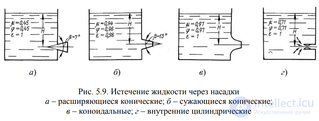
Fig. 5.9. Discharge of liquid through nozzles
a – diverging conical; b – converging conical;
c – conoidal; d – internal cylindrical
Converging conical and conoidal nozzles are used where it is
necessary to obtain a good compact jet of relatively great
length with low energy losses (in pressure fire hoses,
hydraulic monitors, etc.). Converging conical nozzles are used to
increase the discharge flow rate at low exit velocities.
Let us consider the case of emptying a vessel open to the atmosphere under a
continuously decreasing head, in which the flow is
unsteady (Fig. 5.10).
However, if the head, and consequently the discharge velocity,
changes slowly, then the motion at each instant of time can be
regarded as steady, and the Bernoulli equation can be applied to solve
the problem.
Let us denote the variable level height of the liquid in the vessel as h,
the cross-sectional area of the reservoir at that level as S, the orifice area as So, and
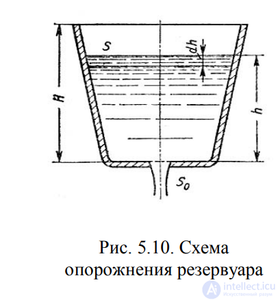
Fig. 5.10. Diagram of reservoir emptying
taking an infinitesimal time interval dt, we can write the following
volume equation:
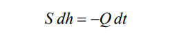
or
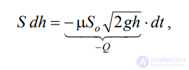
where dh is the change in liquid level over time
dt.
From this, the time for complete emptying
of a vessel of height H
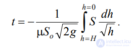 (5.15)
If the law governing the change of area S with height h is known, then
integral (5.15) can be evaluated. For a prismatic vessel S = const
(Fig. 5.11), and hence the time of its complete emptying
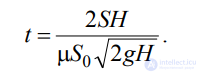 . (5.16)
From expression (5.16) it follows that the time of complete emptying
of a prismatic vessel is twice the time required to discharge the same
volume of liquid at a constant head equal to the initial one.
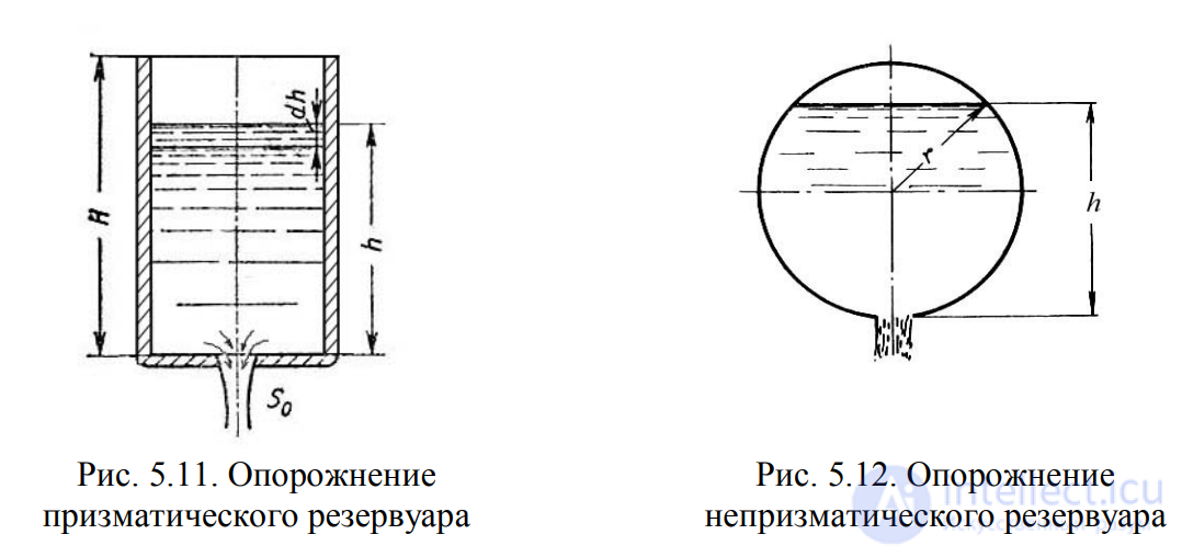
Fig. 5.11. Emptying of a prismatic reservoir
Fig. 5.12. Emptying of a non-prismatic reservoir
To determine the time of liquid discharge from a horizontal
cylindrical vessel (tank car) (Fig. 5.12), let us express the dependence of the
variable area S on h:
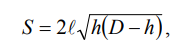
where is the length of the tank; D is the diameter of the tank.
Then the time of complete emptying of such a tank, i.e. the time
for the head to change from h1 = D to h2 = 0, is found to equal
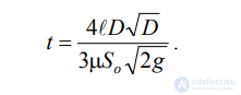 . (5.17)
In many water-intake and water-conveyance hydraulic engineering
structures, water flow rates pass through orifices closed by
gates. Gates are raised to a certain height above the bottom and
allow the required flow rates to pass through the orifices. Most often, at
land-reclamation hydraulic structures, orifices of rectangular
cross-section are provided, and it is the discharge from these that we shall consider.
Orifices may be unsubmerged (free discharge) or
submerged, when the water level downstream of the gate affects the discharge.
If the orifice is unsubmerged, the jet flowing out from under the gate
is under atmospheric pressure (Fig. 5.13). During discharge through a
submerged orifice, the jet behind the gate is under a certain layer of
water (Fig. 5.14).
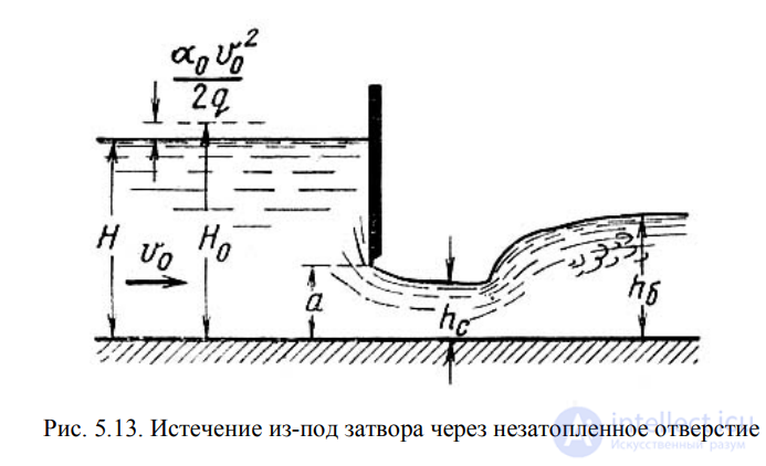
Fig. 5.13. Discharge from under a gate through an unsubmerged orifice
When the gate is raised above the bottom, the jet flowing out from under it
undergoes contraction in the vertical plane. At a distance approximately
equal to the height of the opening a (the height to which the gate is raised), the
most contracted cross-section is observed. The depth at the contracted section hc is related to the height
of the opening a by the following relationship:
 (5.18)
where is the coefficient of vertical contraction of the jet.
The coefficient of vertical contraction depends on the ratio of the
opening height a to the head (depth of water in front of the gate) H. For
approximate calculations, one can take = 0.64.
If we write the Bernoulli equation for the sections taken before the
gate and at the contracted section, after transformation we obtain:
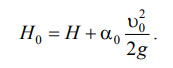
 , (5.19)
where is the velocity coefficient,
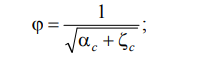
H0 is the head taking into account the approach velocity,
Then the flow rate for discharge from under a gate with an unsubmerged
orifice is determined by the formula:
 , (5.20)
where S is the area of the orifice, S = ab.
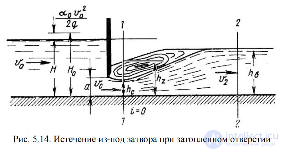
Fig. 5.14. Discharge from under a gate with a submerged orifice
During discharge through a submerged orifice (Fig. 5.14), the flow rate
is determined by the formula:
 , (5.21)
where hz is the depth at the cross-section where the maximum contraction
of the jet flowing out from under the gate is observed.
The depth hz
is determined from the relationship
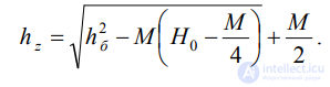 (5.22)
in which
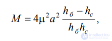
and hb is the depth in the downstream channel (tailwater depth).
If a jet flowing out of an orifice or nozzle
strikes a stationary wall, it exerts a certain pressure on
it. The basic equation used to calculate the pressure of the jet on
a surface has the form
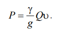 . (5.23)
Fig. 5.15 shows the most commonly encountered
confining surfaces (obstacles) in practice and the equations by which
the pressure of the jet on the corresponding surface is calculated.
The magnitude of the jet pressure naturally depends on the distance
from the nozzle to the obstacle. As the distance increases, the jet disperses and
the pressure decreases. Corresponding studies show that in
this case the jet can be divided into three characteristic parts:
a compact part, a broken-up part, and an atomized part (Fig. 5.16).
Within the compact part, the jet retains its cylindrical shape
without disruption of the continuity of motion. Within the broken-up
part, the continuity of the flow is disrupted, and the jet gradually
expands. Finally, within the atomized part of the jet,
the flow finally breaks up into individual droplets.
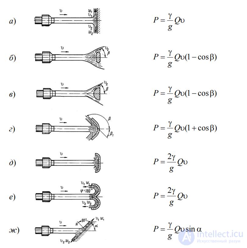
Fig. 5.15. Interaction of a liquid jet with a stationary surface
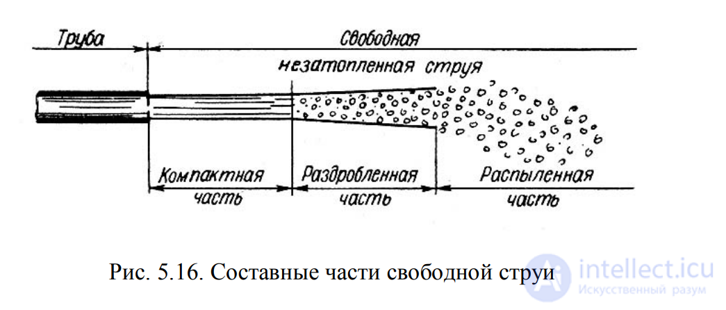
Fig. 5.16. Component parts of a free jet

Comments