Lecture
Timers have their own reserved memory area in your CPU. This memory area reserves one 16-bit word for each timer address. The instruction set of the contact plan supports 256 timers. To set the number of available timer words, refer to the technical description of your CPU.
The following functions have access to the timer memory area:
Bits 0 through 9 in the timer word contain the time value in binary
code. The time value specifies the number of units. Timer update
decreases the time value by one unit over a time interval,
set by time base. The time value is reduced until
until it becomes zero. You can load the time value in
low word of accumulator 1 in binary, hexadecimal or
Binary Coded Decimal (BCD) code (see figure). Time span covers
values from 0 to 9 990 seconds. 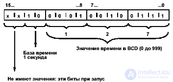
Fig. 4_1
You can preload a time value using any of the following formats:
The maximum time you can enter is 9 990 seconds or 2H_46M_30S.
There are certain restrictions on the placement of all timer blocks (see the elements and blocks section).
Bits 12 and 13 in the timer word contain the time base in binary code. The time base defines the interval at which the time value decreases by one unit (see Table 4-1 and Figure 4-1). The minimum time base is 10 ms; maximum - 10 s.
| Time base | Binary code for time base |
| 10 ms | 00 |
| 100 ms | 01 |
| 1 s | ten |
| 10s | eleven |
table 4_1
Since time values are remembered only after one time interval, values that are not exact multiples of the time interval are truncated. Values whose resolution is too large for the desired range are rounded so that the desired range is achieved, but not the desired resolution. The following table shows the possible resolutions and their corresponding ranges.
| Resolution | Range |
| 0.01 seconds | 10MS to 9S_990MS |
| 0.1 seconds | from 100MS to 1M_39S_900MS |
| 1 second | from 1S to 16M_39S |
| 10 Seconds | from 10S to 2HR_46M_30S |
When the timer starts, the contents of the timer cell are used as the time value. Bits 0 through 11 in the timer cell contain the time value in binary coded decimal format (BCD – format: each group of four bits contains the binary code of one decimal place). Bits 12 and 13 contain the time base in binary code (see Table 4_1). Fig. 4_1 shows the contents of the timer cell loaded with the value of timer 127 with a base time of 1 second.
Each timer block provides two outputs, BI and BCD, for which you can specify the address of a word. The time value at the BI output is in binary format. The time base and time value at the output of a BCD are presented in a binary decimal format (BCD).
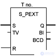
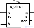
The following figure gives an overview of the five types of timers described in this chapter. This review should help you choose a timer that matches your goals.
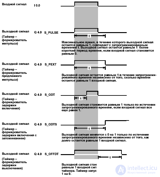
The Timer S5 command — the pulse shaper triggers the specified timer if there is a positive edge (that is, a change in the signal state from 0 to 1) at the S input (Start). Changing the signal is always necessary to start the timer. The timer continues to operate with the time specified at the TV input (Time Value) until the programmed time has elapsed if the signal state at TV input is 1. While the timer is running, output Q gives a result of 1. If input S there is a change from 1 to 0 before the expiration of the specified time, the timer stops. Then the state of the signal at the output Q gives a result equal to 0.
Changing from 0 to 1 at the input of the timer R (Reset [Reset]) while the timer is running resets the timer. This change also resets to zero time and time base. The states of signal 1 at the input of timer R have no effect if the timer does not work.
The current time value can be read at the BI and BCD outputs. The time value on BI is represented in binary code, and at the output of the BCD - in binary-decimal code.
| LAD element | Parameter | Type of data | Memory area | Description |
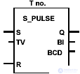 | no. | TIMER | T | An identification number timer Range depends on CPU. |
| S | Bool | I, Q, M, D, L, T, C | Launch input | |
| Tv | S5TIME | I, Q, M, D, L | Preset value of time (range from 0 to 9999) | |
| R | Bool | I, Q, M, D, L, T, C | Reset input | |
| Q | Bool | I, Q, M, D, L | Timer state | |
| BI | WORD | I, Q, M, D, L | Time remaining (integer format) | |
| BCD | WORD | I, Q, M, D, L | Remaining time (BCD format) |
Bits of the status word and characteristics of the timer - pulse shaper.
Certain restrictions are imposed on the placement of timer blocks (see Section 1.1).
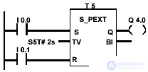
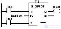
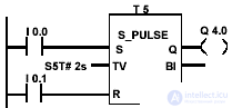 | If the state of the signal at input I 0.0 changes from 0 to 1 (that is, there is a positive edge in RLO), timer T 5 starts. The timer continues to operate with the specified time of 2 seconds until input I 0.0 is 1. If the state of the signal at input I 0.0 changes from 1 to 0 before the time expires, the timer stops. If the state of the signal at input I 0.1 changes from 0 to 1 when the timer is running, the timer is reset. The state of the signal at output Q 4.0 is 1, while the timer is running. Examples of other preset values time: Possible units: h (hours), m (minutes), s (seconds) ms (milliseconds) S5T # 4s -> 4 seconds S5T # 1h_15m -> 1 hour and 15 minutes S5T # 2h_46m_30s -> 2 hours, 46 minutes and 30 seconds |
| Status word bits | |||||||||
| BR | CC 1 | CC 0 | Ov | OS | OR | Sta | Rlo | FC | |
| Record | - | - | - | - | - | x | x | x | one |
| Timing chart | |||||||||
RLO inlet S RLO inlet R Timer operation Interrogation of signal state on 1 Poll signal state to 0 | 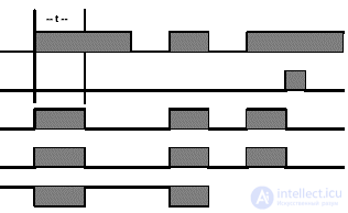 t = programmed time | ||||||||
The Timer S5 command — the extended pulse shaper triggers the specified timer if there is a positive edge (that is, a change in signal state from 0 to 1) at input S (Start). Changing the signal is always necessary to start the timer. The timer continues to operate with the time specified at the TV input (Time Value), even if the state of the signal at input S changes to 0 before the time expires. While the timer is running, the state of the signal at output Q gives a result of 1. The timer restarts with the specified time if the state of the signal at input S changes from 0 to 1 while the timer is running. Changing from 0 to 1 at the input of the timer R (Reset [Reset]) while the timer is running resets the timer. This change also resets to zero time and time base.
The current time value can be read at the BI and BCD outputs. The time value on BI is represented in binary code, and at the output of the BCD - in binary-decimal code.
| LAD element | Parameter | Type of data | Memory area | Description |
 | no. | TIMER | T | An identification number timer Range depends on CPU. |
| S | Bool | I, Q, M, D, L, T, C | Launch input | |
| Tv | S5TIME | I, Q, M, D, L | Preset value of time (range from 0 to 9999) | |
| R | Bool | I, Q, M, D, L, T, C | Reset input | |
| Q | Bool | I, Q, M, D, L | Timer state | |
| BI | WORD | I, Q, M, D, L | Time remaining (integer format) | |
| BCD | WORD | I, Q, M, D, L | Remaining time (BCD format) |
The bits of the status word and the characteristics of the timer of the extended pulse.
There are certain restrictions on the placement of all timer blocks (see Section 1.1).
 | If the state of the signal at input I 0.0 changes from 0 to 1 (that is, there is a positive edge in the RLO), timer T 5 starts. The timer continues to operate with the specified time of 2 seconds, even if there is a negative edge at input S. If the state of the signal at input I 0.0 changes from 0 to 1 before the specified time has elapsed, the timer is restarted. If the state of the signal at input I 0.1 changes from 0 to 1, when the timer is running, the timer is reset. The state of the signal at output Q 4.0 is 1, while the timer is running |
| Status word bits | |||||||||
| BR | CC 1 | CC 0 | Ov | OS | OR | Sta | Rlo | FC | |
| Record | - | - | - | - | - | x | x | x | one |
| Timing chart | |||||||||
RLO inlet S RLO inlet R Timer operation Interrogation of signal state on 1 Poll signal state to 0 | 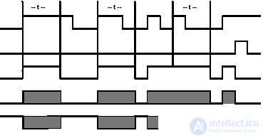 t = programmed time | ||||||||
The Timer S5 command - with the on delay, starts the specified timer if there is a positive edge (i.e., a change in the signal state from 0 to 1) at input S. A change in the signal is always necessary to start the timer. The timer continues to work with the time indicated on the TV input until the signal state at input S is 1. The signal state at output Q gives a result equal to 1 when the time has expired without errors, and the signal state at input S is still 1. When time of the timer state of the signal at input S changes from 1 to 0, the timer stops. In this case, the signal state at the output Q always gives a result equal to 0.
A change from 0 to 1 at the input of timer R while the timer is running resets the timer. This change also resets to zero time and time base. The timer is also reset if the state of the signal at input R is 1 when the timer is not running.
The current time value can be read at the BI and BCD outputs. The time value on BI is represented in binary code, and at the output of the BCD - in binary-decimal code.
| LAD element | Parameter | Type of data | Memory area | Description |
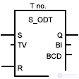 | no. | TIMER | T | An identification number timer Range depends on CPU. |
| S | Bool | I, Q, M, D, L, T, C | Launch input | |
| Tv | S5TIME | I, Q, M, D, L | Preset value of time (range from 0 to 9999) | |
| R | Bool | I, Q, M, D, L, T, C | Reset input | |
| Q | Bool | I, Q, M, D, L | Timer state | |
| BI | WORD | I, Q, M, D, L | Time remaining (integer format) | |
| BCD | WORD | I, Q, M, D, L | Remaining time (BCD format) |
Bits of the status word and the characteristics of the timer with a delay on.
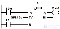 | If the state of the signal at input I 0.0 changes from 0 to 1 (that is, there is a positive edge in the RLO), timer T 5 starts. If the specified time expires for 2 seconds and the state of the signal at input I 0.0 is still 1, the state of the signal at output Q 4.0 is 1. If the state of the signal at input I 0.0 changes from 1 to 0, then the timer stops and the output Q 4.0 equals 0. If the state of the signal at input I 0.1 changes from 0 to 1 while the timer is running, the timer is reset. |
| Status word bits | |||||||||
| BR | CC 1 | CC 0 | Ov | OS | OR | Sta | Rlo | FC | |
| Record | - | - | - | - | - | x | x | x | one |
| Timing chart | |||||||||
RLO inlet S RLO inlet R Timer operation Interrogation of signal state on 1 Poll signal state to 0 |  t = programmed time | ||||||||
The Timer S5 command - with a power-on delay and memorization, starts the specified timer if there is a positive RLO front (from 0 to 1) at input S. A signal change is always necessary to start the timer. The timer continues to work with the time specified at the TV input, even if the state of the signal at input S changes to 0 before the specified time has passed. The state of the signal at the output Q gives a result equal to 1 when the time has expired regardless of the state of the signal at input S, if the reset input (R) remains equal to 0. The timer restarts with the specified time if the state of the signal at input S changes from 0 to 1 during timer time.
Changing from 0 to 1 at the input of the timer R (Reset [Reset]) resets the timer regardless of the RLO at input S.
| LAD element | Parameter | Type of data | Memory area | Description |
 | no. | TIMER | T | An identification number timer Range depends on CPU. |
| S | Bool | I, Q, M, D, L, T, C | Launch input | |
| Tv | S5TIME | I, Q, M, D, L | Preset value of time (range from 0 to 9999) | |
| R | Bool | I, Q, M, D, L, T, C | Reset input | |
| Q | Bool | I, Q, M, D, L | Timer state | |
| BI | WORD | I, Q, M, D, L | Time remaining (integer format) | |
| BCD | WORD | I, Q, M, D, L | Remaining time (BCD format) |
Status word bits and timer characteristics with on-delay and remembering
 | If the state of the signal at input I 0.0 changes from 0 to 1 (that is, there is a positive edge in the RLO), then timer T 5 starts. The timer continues to work, ignoring the change in input I 0.0 from 1 to 0. If the state of the signal at input I 0.0 changes from 0 to 1 before the expiration of the specified time, the timer is restarted. If the state of the signal at input I 0.1 changes from 0 to 1 while the timer is running, the timer is reset. The state of the signal at output Q 4.0 is 1, regardless of the state of the signal at I 0.1 |
| Status word bits | |||||||||
| BR | CC 1 | CC 0 | Ov | OS | OR | Sta | Rlo | FC | |
| Record | - | - | - | - | - | x | x | x | one |
| Timing chart | |||||||||
RLO inlet S RLO inlet R Timer operation Interrogation of signal state on 1 Poll signal state to 0 | 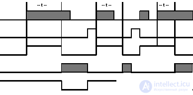 t = programmed time | ||||||||
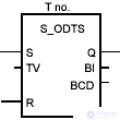
The Timer S5 command - with a shutdown delay, starts the specified timer if there is a negative edge (that is, a change in the signal state from 1 to 0) at input S. Changing the signal is always necessary to start the timer. The state of the signal at output Q is 1 when it is equal to 1 the state of the signal at input S or if the timer is running. The timer is reset when the state of the signal at input S changes from 0 to 1 while the timer is running. The timer does not restart until the state of the signal at input S changes again from 1 to 0.
A change from 0 to 1 at the input of timer R while the timer is running resets the timer.
The current time value can be read at the BI and BCD outputs. The time value on BI is represented in binary code, and at the output of the BCD - in binary-decimal code.
| LAD element | Parameter | Type of data | Memory area | Description |
 | no. | TIMER | T | An identification number timer Range depends on CPU. |
| S | Bool | I, Q, M, D, L, T, C | Launch input | |
| Tv | S5TIME | I, Q, M, D, L | Preset value of time (range from 0 to 9999) | |
| R | Bool | I, Q, M, D, L, T, C | Reset input | |
| Q | Bool | I, Q, M, D, L | Timer state | |
| BI | WORD | I, Q, M, D, L | Time remaining (integer format) | |
| BCD | WORD | I, Q, M, D, L | Remaining time (BCD format) |
Status word bits and timer delayed shutdown characteristics
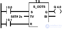
 | If the state of the signal at input I 0.0 changes from 1 to 0 (that is, there is a negative edge in the RLO), then the timer starts. The state of the signal at the output of Q 4.0 is 1, when the state of the signal on I 0.0 is 1 or timer works. If the state of the signal at input I 0.1 changes from 0 to 1 during timer operation, the timer is reset. |
| Status word bits | |||||||||
| BR | CC 1 | CC 0 | Ov | OS | OR | Sta | Rlo | FC | |
| Record | - | - | - | - | - | x | x | x | one |
| Timing chart | |||||||||
RLO inlet S RLO inlet R Timer operation Interrogation of signal state on 1 Poll signal state to 0 | 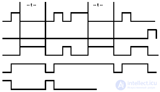 t = programmed time | ||||||||

Comments