Lecture
Bit logic operations work with two digits: 1 and 0. These two digits form the base of the number system, called the binary system. The two digits 1 and 0 are called binary digits or bits. In the world of contacts and coils, 1 means active state or current flow, and 0 means inactive state or no current flow. Bit logic operations interpret the signal states 1 and 0 and match them in accordance with the rules of Boolean logic. These conjugations give a result of 1 or 0, which is called the “result of a logical operation” (RLO). Logical operations triggered by bit logic commands perform a number of functions.
There are bit logic commands to perform the following functions:
The Normally Open Contact command can be used to interrogate the signal state of a contact at a specified address. If the signal state at the specified address is 1, then the contact is closed, and the command gives a result equal to 1. If the signal state at the specified address is 0, then the contact is open, and the command gives a result equal to 0.
When a Normally Open contact (address) is the first command in a logic circuit, this command stores the result of polling the signal in a bit of the result of a logical operation (RLO). Any command A normally open contact (address) that is not the first in the logic circuit matches the result of the signal state polling with the value stored in the RLO bit. This command forms a pairing in one of the following two ways:
| LAD element | Parameter | Type of data | Memory area | Description |
| <address> - | | | - | <address> | BOOL, TIMER, COUNTER | I, Q, M, T, C, D, L | The address indicates a bit whose signal state is polled. |
Example and Status Word Bits
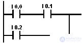 | The current flows if one of the following conditions is met: 1 is equal to the state of the signal at the inputs I 0.0 and I 0.1 OR equal to 1 the state of the signal at the input I 0.2 |
| Status word bits | |||||||||
| BR | CC 1 | CC 0 | Ov | OS | OR | Sta | Rlo | FC | |
| Record | - | - | - | - | - | x | x | x | one |
In fact, a normally closed contact is the inverse of the command A normally open contact. That is, if the signal at the specified address is 0, then the contact is closed and gives 1. If the signal at the specified address is 1, then the contact is open and does not pass current, they are output 0.
Using a normally closed contact in parallel you will get a logical function I.
| LAD element | Parameter | Type of data | Memory area | Description |
| <address> - | / | - | <address> | BOOL, TIMER, COUNTER | I, Q, M, T, C, D, L | The address indicates a bit whose signal state is polled. |
Example and Status Word Bits
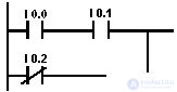 | The current flows if one of the following conditions is met: 1 is equal to the state of the signal at inputs I 0.0 and I 0.1 OR is 0 the state of the signal at input I 0.2 |
| Status word bits | |||||||||
| BR | CC 1 | CC 0 | Ov | OS | OR | Sta | Rlo | FC | |
| Record | - | - | - | - | - | x | x | x | one |
The Output Coil command works like a coil in a ladder circuit. The coil at the end of the circuit passes or does not pass current, depending on the following criteria:
The chain of logical operations represents the current circuit. The Output Coil command assigns the signal state of the LAD logic circuit to the coil to which the command is addressed (this is the same as assigning the signal state of the RLO bit to the operand). If the current flows through the circuit, the signal state of the logic circuit is 1; otherwise, the signal state is 0.
The Output Coil command is affected by the Master Control Relay (MCR).
The output coil can only be placed at the right end of the logic circuit. It is possible to use multiple output coils. The output coil cannot be placed alone in an empty segment. The coil must have a prior connection. You can also invert the output using the invert output command .
| LAD element | Parameter | Type of data | Memory area | Description |
 | <address> | Bool | I, Q, M, D, L | The address indicates a bit whose signal state is polled. |
Example and Status Word Bits
| The state of the Q 4.0 output signal is 1 if one of the following conditions is true: 1 is equal to the state of the signal at inputs I 0.0 and I 0.1 OR equal to 0 the state of the signal at input I 0.2 The state of the Q4.1 output signal is 1 if one of the following conditions is true: Equal to 1, the state of the signal at inputs I 0.0 and I 0.1 and I 0.3. OR is equal to 0 state of signal at input I 0.2 and 1 at input I 0.3 |
| Status word bits | |||||||||
| BR | CC 1 | CC 0 | Ov | OS | OR | Sta | Rlo | FC | |
| Record | - | - | - | - | - | 0 | x | - | 0 |
An intermediate output (connector) is an intermediate assignment element that stores a bit logical combination of the last open branch in front of this element. When connected in series with other contacts, the intermediate output (connector) acts like a normal contact.
The Intermediate Output command is affected by the Master Control Relay (MCR).
The connector cannot be placed at the end of a segment or at the end of an open branch.
You can also invert the output.
| LAD element | Parameter | Type of data | Memory area | Description |
 | <address> | Bool | I, Q, M, D, L | The address indicates the bit to which the RLO is assigned. |
For the Intermediate output (connector) command, you can only use the address from the memory area L, only if you describe it in VAR_TEMP. With this command, you cannot use the memory region L for absolute addressing.
Example and Status Word Bits
 The following intermediate outputs have the following RLO: | |
| M 0.0 has an RLO circuit |  |
| M 1.1 has an RLO circuit | 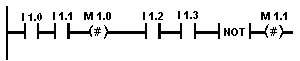 |
| M 2.2 has RLO of the entire bit logic combination. | |
| Status word bits | |||||||||
| BR | CC 1 | CC 0 | Ov | OS | OR | Sta | Rlo | FC | |
| Record | - | - | - | - | - | 0 | x | - | one |
The command Invert the result of a logical operation ( Invert ) negates the RLO.
| LAD element | Parameter | Type of data | Memory area | Description |
| - | NOT | - | not | - | - | - |
Example and Status Word Bits
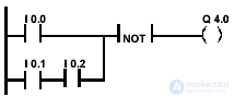 | Output Q 4.0 is 1 if one of the following conditions is true: The state of the signal at input I 0.0 is NOT equal to 1 OR the state of the signal is NOT equal to 1 at input I 0.1 or at input I 0.2 or both. |
| Status word bits | |||||||||
| BR | CC 1 | CC 0 | Ov | OS | OR | Sta | Rlo | FC | |
| Record | - | - | - | - | - | - | one | - | - |
This command stores the RLO in the BR bit of the status word. The initial polling bit FC is not reset.
For this reason, the state of the BR bit is included in the logical AND operation in the next segment.
We do not recommend you to use SAVE, and then poll the BR bit in the same block or in fixed blocks, since the BR bit can be changed by many commands between these events. It is advisable to use the SAVE command before exiting the block, since the ENO output (= BR bit) is then set to the RLO bit value, and you can then monitor the errors in the block.
| LAD element | Parameter | Type of data | Memory area | Description |
 | not | - | - | - |
Example and Status Word Bits
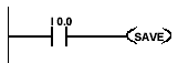 | The circuit status (= RLO) is stored in the BR bit before calling FC10. |
| Status word bits | |||||||||
| BR | CC 1 | CC 0 | Ov | OS | OR | Sta | Rlo | FC | |
| Record | x | - | - | - | - | - | - | - | - |
Setting the output is performed only when RLO = 1. If RLO = 1, this command sets the specified address to 1. If RLO = 0, the command does not affect the specified address. The address remains unchanged.
The Output Setup command is affected by the Master Control Relay (MCR).
| LAD element | Parameter | Type of data | Memory area | Description |
| - (S) | <address> | Bool | I, Q, M, D, L | The address indicates the bit that must be installed. |
Example and Status Word Bits
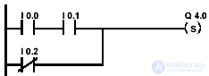 | The state of the signal at output Q 4.0 is set to 1 if one of the following conditions is true: Equal to 1, the state of the signal at inputs I 0.0 and I 0.1 OR is 0 the state of the signal at input I 0.2. If the RLO branch is 0, then the signal state at the output of Q 4.0 does not change. |
| Status word bits | |||||||||
| BR | CC 1 | CC 0 | Ov | OS | OR | Sta | Rlo | FC | |
| Record | - | - | - | - | - | 0 | x | - | 0 |
The output is reset only when RLO = 1. If RLO = 1, this command resets the specified address to 0. If RLO = 0, the command does not affect the specified address and it remains unchanged.
The Output Reset command is affected by the Master Control Relay (MCR).
| LAD element | Parameter | Type of data | Memory area | Description |
| <Address> - (R) | <address> | BOOL, TIMER, COUNTER | I, Q, M, T, C, D, L | The address indicates the bit that must be reset. |
Example and Status Word Bits
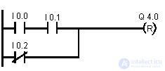 | The state of the signal at output Q 4.0 is reset to 0 if one of the following conditions is fulfilled: Equal 1 is the state of the signal at inputs I 0.0 and I 0.1 OR is 0 the state of the signal at input I 0.2 If the RLO of the branch is 0, then the state of the signal at output Q 4.0 does not change.. |
| Status word bits | |||||||||
| BR | CC 1 | CC 0 | Ov | OS | OR | Sta | Rlo | FC | |
| Record | - | - | - | - | - | 0 | x | - | 0 |
You can use the Set Initial Counter Value (SC) command to place a predefined value in the counter you specify. The command is executed only when the RLO edge is positive (that is, a transition from 0 to 1 takes place in RLO).
| LAD element | Parameter | Type of data | Memory area | Description |
 | counter number | COUNTER | WITH | The address indicates the number of the counter in which the initial value should be set. |
| Predust innovation value | - | I, Q, M, D, L | The initial value may be in the range of 0 to 999. The value must be preceded by C #, which indicates a binary-decimal format (BCD), for example, C # 100. |
Example and Status Word Bits
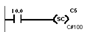 | If the state of the signal at input I 0.0 changes from 0 to 1 (that is, there is a positive edge in the RLO), the initial value is set in the counter C 5 100. C # indicates that you enter a value in BCD format. When you save the chain, this value will be presented on your screen as w # 16 # 100. If the positive edge is absent, then the value of the counter C 5 does not change. |
| Status word bits | |||||||||
| BR | CC 1 | CC 0 | Ov | OS | OR | Sta | Rlo | FC | |
| Record | - | - | - | - | - | 0 | x | - | 0 |
A coil with a direct counting counter (CU) increases the value of the specified counter by one if the RLO has a positive front (i.e. a transition from 0 to 1 occurs in the RLO) and the counter value is less than 999. If the positive RLO front is absent or the counter has already reached 999, the counter value does not change.
You can also set the initial value of the counter using the Set the initial value of the counter command
| LAD element | Parameter | Type of data | Memory area | Description |
| <Address> - (CU) | counter number | COUNTER | C | The address indicates the number of the counter whose contents need to be increased. |
Example and Status Word Bits
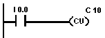 | If the state of the signal at input I 0.0 changes from 0 to 1 (ie, a positive edge occurs in RLO), then the value of the counter C 10 is increased by 1 (if the value of C 10 is not equal to 999). If there is no positive edge, then the value of C 10 does not change. |
| Status word bits | |||||||||
| BR | CC 1 | CC 0 | Ov | OS | OR | Sta | Rlo | FC | |
| Record | - | - | - | - | - | 0 | - | - | 0 |
A coil with a countdown counter (CD) decreases the value of the specified counter by one if the RLO has a positive edge (i.e. a transition from 0 to 1 occurs in the RLO) and the counter value is greater than 0. If the RLO positive edge is absent or the counter is already 0, the counter value does not change.
You can also set the initial value of the counter using the Set the initial value of the counter command
| LAD element | Parameter | Type of data | Memory area | Description |
| <Address> - (CD) | counter number | COUNTER | C | The address indicates the number of the counter whose contents need to be reduced. |
Example and Status Word Bits
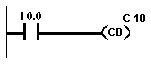 | If the state of the signal at input I 0.0 changes from 0 to 1 (that is, there is a positive edge in RLO), then the value of the counter C 10 decreases by 1 (if the value of C 10 is not equal to 0). If there is no positive front, then C 10 does not change. |
| Status word bits | |||||||||
| BR | CC 1 | CC 0 | Ov | OS | OR | Sta | Rlo | FC | |
| Record | - | - | - | - | - | 0 | - | - | 0 |
A coil with a timer-shaper (SP) starts the specified timer with the specified time value if the RLO has a positive edge. The timer continues to operate with the specified time, while the RLO value is positive. Interrogating the state of the timer signal at 1 gives a result equal to 1 while the timer is running. If the RLO changes from 1 to 0 before the specified time has elapsed, then the timer stops. In this case, polling the signal state by 1 gives a result equal to 0.
The time units are d (days), h (hours), m (minutes), s (seconds) and ms (milliseconds). For information on placing the timer in memory and its components, refer to Section 4.
| LAD element | Parameter | Type of data | Memory area | Description |
| <Address> - (SP) <Time value> | timer number | TIMER | T | The address indicates the number of the timer to be started. |
| Value of time | S5TIME | I, Q, M, D, L | Time value (in format S5TIME) |
Example and Status Word Bits
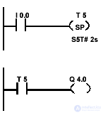 | If the state of the signal at input I 0.0 changes from 0 to 1 (that is, a positive edge occurs in RLO), then timer T 5 starts. The timer continues to operate with the specified time of 2 seconds until the state of the signal at input I 0.0 is 1. If the state of the signal at input I 0.0 changes from 1 to 0 before the specified time has elapsed, it stops. The state of the signal at output Q 4.0 is 1, while the timer is running. Examples of time values: S5T # 2s = 2 seconds S5T # 12m_18s = 12 minutes and 18 seconds |
| Status word bits | |||||||||
| BR | CC 1 | CC 0 | Ov | OS | OR | Sta | Rlo | FC | |
| Record | - | - | - | - | - | 0 | - | - | 0 |
A coil with a timer-shaper extended pulse (SE) starts the specified timer with the specified time value if the RLO has a positive edge. The timer continues to operate with the specified time, even if the RLO becomes 0 before this time expires. Interrogating the state of the timer signal at 1 gives a result equal to 1 while the timer is running. If the RLO changes from 0 to 1 while the timer is running, the timer restarts with the specified time.
For information about placing the timer in memory and its components, see Section 4.
| LAD element | Parameter | Type of data | Memory area | Description |
| <Address> - (SE) <Time value> | timer number | TIMER | T | The address indicates the number of the timer to be started. |
| Value of time | S5TIME | I, Q, M, D, L | Time value (in format S5TIME) |
Example and Status Word Bits
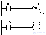 | If the state of the signal at I 0.0 changes from 0 to 1 (that is, a positive edge occurs in the RLO), then timer T 5 starts. The timer continues to run despite the negative front in the RLO. If the state of the signal on I 0.0 changes from 0 to 1 before the expiration of the specified time, the timer is restarted. The state of the signal at output Q 4.0 is 1, while the timer is running. |
| Status word bits | |||||||||
| BR | CC 1 | CC 0 | Ov | OS | OR | Sta | Rlo | FC | |
| Record | - | - | - | - | - | 0 | - | - | 0 |
Катушка с таймером – формирователем задержки включения (SD) запускает указанный таймер, если RLO имеет положительный фронт (т.е. в RLO имеет место переход с 0 на 1). Опрос состояния таймера на 1 дает результат, равный 1, когда указанное время истекло без ошибок, а RLO еще равен 1. Когда RLO изменяет свое значение с 1 на 0 во время работы таймера, таймер останавливается.
| Элемент LAD | Параметр | Type of данных | Область памяти | Description |
| <Адрес> —(SD) <Значение времени> | номер таймера | TIMER | T | Адрес указывает номер таймера, который должен быть запущен. |
| Value of time | S5TIME | I, Q, M, D, L | Значение времени (в формате S5TIME) |
Пример и биты слова состояния
 | Если состояние сигнала на входе I 0.0 меняется с 0 на 1 (т.е. имеет место положительный фронт в RLO), то таймер Т 5 запускается Если время истекло, а cостояние сигнала на входе I 0.0 еще равно 1, то выход Q 4.0 равен 1. Если состояние сигнала на входе I 0.0 меняется с 1 на 0, то таймер останавливается, а выход Q 4.0 становится равным 0. |
| Биты слова состояния | |||||||||
| BR | CC 1 | CC 0 | OV | OS | OR | STA | RLO | FC | |
| Record | - | - | - | - | - | 0 | - | - | 0 |
Катушка с таймером – формирователем задержки включения с запоминанием (SS) запускает указанный таймер, если RLO имеет положительный фронт . Таймер продолжает работать с указанным временем, даже если RLO меняется на 0 до истечения времени. Опрос состояния таймера на 1 дает результат, равный 1, когда время истекло, независимо от RLO. Таймер перезапускается с заданным временем, если во время работы таймера RLO меняется с 0 на 1.
За информацией о размещении таймера в памяти и его компонентах обратитесь к разделу 4
| Элемент LAD | Параметр | Type of данных | Область памяти | Description |
| <Адрес> —(SS) <Значение времени> | номер таймера | TIMER | T | Адрес указывает номер таймера, который должен быть запущен. |
| Value of time | S5TIME | I, Q, M, D, L | Значение времени (в формате S5TIME) |
Пример и биты слова состояния
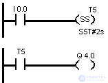 | Если состояние сигнала на входе I0.0 меняется с 0 на 1 (нарастающий фронт на RLO), таймер T5 запускается. Таймер продолжает работать независимо от того, меняется ли состояние сигнала на I0.0 с 1 на 0. Если состояние сигнала меняется с 0 на 1 до истечения заданного времени, таймер перезапускается. Выход Q4.0 получает значение 1, когда время истекает. |
| Биты слова состояния | |||||||||
| BR | CC 1 | CC 0 | OV | OS | OR | STA | RLO | FC | |
| Record | - | - | - | - | - | 0 | - | - | 0 |
Катушка с таймером – формирователем задержки выключения (SF) запускает указанный таймер, если RLO имеет отрицательный фронт (т.е. в RLO имеет место переход с 1 на 0). Результат опроса состояния сигнала таймера на 1 равен 1, когда RLO равен 1 или когда таймер работает. Когда RLO изменяется с 0 на 1 во время работы таймера, таймер сбрасывается. Таймер не перезапускается, пока RLO не поменяет свое значение с 1 на 0.
| Элемент LAD | Параметр | Type of данных | Область памяти | Description |
| <Адрес> —(SF) <Значение времени> | номер таймера | TIMER | T | Адрес указывает номер таймера, который должен быть запущен. |
| Value of time | S5TIME | I, Q, M, D, L | Значение времени (в формате S5TIME) |
Пример и биты слова состояния
 | If the state of the signal at input I 0.0 changes from 1 to 0, then the timer starts. If the state of the signal at input I 0.0 changes from 0 to 1, then the timer is reset. The state of the signal at output Q 4.0 is 1 when the state of the signal at input I 0.0 is 1, or when the timer is running. |
| Status word bits | |||||||||
| BR | CC 1 | CC 0 | Ov | OS | OR | Sta | Rlo | FC | |
| Record | - | - | - | - | - | 0 | - | - | 0 |
Операция Обнаружение положительного фронта RLO распознает изменение во введенном адресе с 0 на 1 (нарастающий фронт) и отображает это после выполнения операции как RLO = 1. Текущее состояние сигнала в RLO сравнивается с состоянием сигнала адреса, бита памяти фронта. Если состояние сигнала адреса равно 0, а RLO перед операцией был равен 1, то RLO после операции будет равен 1 (импульс), и 0 во всех остальных случаях. Значение RLO перед операцией хранится в адресе.
| Элемент LAD | Параметр | Type of данных | Область памяти | Description |
| <Адрес> —(P)— | <Адрес> | BOOL | Q, M, D | Адрес указывает на бит памяти фронта, который хранит предыдущее значение RLO. |
Пример и биты слова состояния
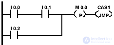 | Бит памяти фронта M 0.0 сохраняет старое состояние RLO от всей битовой логической комбинации. Если имеет место изменение сигнала в RLO с 0 на 1, то программа переходит на метку CAS1. |
| Биты слова состояния | |||||||||
| BR | CC 1 | CC 0 | OV | OS | OR | STA | RLO | FC | |
| Record | - | - | - | - | - | x | x | x | one |
Операция Обнаружение отрицательного фронта RLO распознает изменение во введенном адресе с 1 на 0 (падающий фронт) и отображает это после выполнения операции как RLO = 1. Текущее состояние сигнала в RLO сравнивается с состоянием сигнала адреса, бита памяти фронта. Если состояние сигнала адреса равно 1, а RLO перед операцией был равен 0, то RLO после операции будет равен 0 (импульс), и 1 во всех остальных случаях. Значение RLO перед операцией хранится в адресе.
| Элемент LAD | Параметр | Type of данных | Memory area | Description |
| <Address> - (N) - | <Address> | Bool | Q, M, D | The address points to the edge memory bit, which stores the previous RLO value. |
Example and Status Word Bits
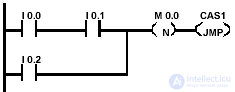 | The front memory bit M 0.0 preserves the old RLO state of the entire logical combination. If it has a signal change on the RLO from 1 to the program goes to the label CAS1. |
| Status word bits | |||||||||
| BR | CC 1 | CC 0 | Ov | OS | OR | Sta | Rlo | FC | |
| Record | - | - | - | - | - | x | x | ||
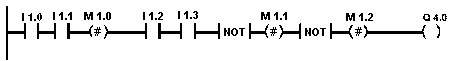
The Positive Signal Edge Detection command compares the signal state <address 1> with the result of polling the signal state stored at <address 2>. If there is a transition from 0 to 1, then the output Q is 1. Otherwise, it is 0.
| LAD element | Parameter | Type of data | Memory area | Description |
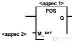 | <Address1> | Bool | I, Q, M, D, L | Сигнал, подлежащий контролю на появление положительного фронта. |
| M_BIT | BOOL | Q, M, D | Адрес M_BIT указывает бит памяти фронта, который хранит предыдущее состояние сигнала POS. Используйте для M_BIT область памяти входов образа процесса (I) только в том случае, если этот адрес уже не занят ни одним из модулей ввода. | |
| Q | BOOL | I, Q, M, D, L | Выход с однократным импульсом. |
Пример и биты слова состояния
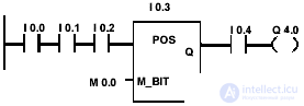 | Выход Q 4.0 равен 1, если выполняются следующие условия: Равно 1 состояние сигнала на входах I 0.0 и I 0.1 и I 0.2 и имеется положительный фронт на входе I 0.3 и равно 1 состояние сигнала на входе I 0.4 |
| Биты слова состояния | |||||||||
| BR | CC 1 | CC 0 | OV | OS | OR | STA | RLO | FC | |
| Record | - | - | - | - | - | x | one | x | one |
Команда Обнаружение отрицательного фронта сигнала сравнивает состояние сигнала <адрес 1> с результатом опроса состояния сигнала, хранящимся в <адрес 2>. Если имеет место переход с 1 на 0, то выход Q равен 1. В противном случае он равен 0.
| Элемент LAD | Параметр | Type of данных | Область памяти | Description |
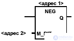 | <Адрес1> | BOOL | I, Q, M, D, L | Сигнал, подлежащий контролю на появление отрицательного фронта. |
| M_BIT | BOOL | Q, M, D | Адрес M_BIT указывает бит памяти фронта, который хранит предыдущее состояние сигнала NEG. Используйте для M_BIT область памяти входов образа процесса (I) только в том случае, если этот адрес уже не занят ни одним из модулей ввода. | |
| Q | BOOL | I, Q, M, D, L | Выход с однократным импульсом. |
Пример и биты слова состояния
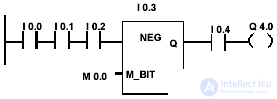 | Выход Q 4.0 равен 1, если выполняются следующие условия: Равно 1 состояние сигнала на входах I 0.0 и I 0.1 и I 0.2 и имеется отрицательный фронт на входе I 0.3 и равно 1 состояние сигнала на входе I 0.4 |
| Биты слова состояния | |||||||||
| BR | CC 1 | CC 0 | OV | OS | OR | STA | RLO | FC | |
| Record | - | - | - | - | - | x | one | x | one |
Команда Установить-сбросить триггер (SR.триггер) выполняет операции установки (S) и сброса (R) только тогда, когда RLO равен 1. RLO, равный 0, не оказывает влияния на эти операции; адрес, указанный в операции, остается неизменным. SR.триггер устанавливается, если состояние сигнала равно 1 на входе S и равно 0 на входе R. В противном случае, если состояние сигнала равно 0 на входе S и 1 на входе R, триггер сбрасывается. Если RLO равен 1 на обоих входах, триггер сбрасывается.
Команда Установить-сбросить триггер испытывает воздействие со стороны Главного управляющего реле (Master Control Relay, MCR).
| Элемент LAD | Параметр | Type of данных | Область памяти | Description |
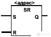 | <Адрес> | BOOL | I, Q, M, D, L | Адрес указывает бит, который должен быть установлен или сброшен. |
| S | BOOL | I, Q, M, D, L | Разрешенная операция установки | |
| R | BOOL | I, Q, M, D, L | Разрешенная операция сброса | |
| Q | BOOL | I, Q, M, D, L | Состояние сигнала <адрес> |
Пример и биты слова состояния
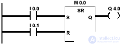 | Если состояние сигнала равно 1 на входе I 0.0 и 0 на входе I 0.1, то бит памяти M 0.0 устанавливается, и выход Q 4.0 равен 1. Если состояние сигнала равно 0 на входе I 0.0 и 1 на входе I 0.1, то бит памяти M 0.0 сбрасывается и Q 4.0 равен 0. Если оба состояния сигнала равны 0, то ничего не меняется. Если оба состояния сигнала равны 1, то операция Сброс имеет преимущество из-за своего расположения, M 0.0 cбрасывается, и Q 4.0 равен 0. |
| Биты слова состояния | |||||||||
| BR | CC 1 | CC 0 | OV | OS | OR | STA | RLO | FC | |
| Record | - | - | - | - | - | x | x | x | one |
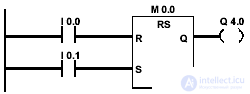
Команда Сбросить-установить триггер (RS.триггер) выполняет операции установки (S) и сброса (R) только тогда, когда RLO равен 1. RLO, равный 0, не оказывает влияния на эти операции; адрес, указанный в операции, остается неизменным. RS.триггер сбрасывается, если состояние сигнала равно 1 на входе R и равно 0 на входе S. В противном случае, если состояние сигнала равно 0 на входе R и 1 на входе S, триггер устанавливается. set. Если RLO равен 1 на обоих входах, триггер устанавливается.
Команда Сбросить-установить триггер испытывает воздействие со стороны Главного управляющего реле (Master Control Relay, MCR).
| Элемент LAD | Параметр | Type of данных | Область памяти | Description |
 | <Адрес> | BOOL | I, Q, M, D, L | Адрес указывает бит, который должен быть установлен или сброшен. |
| R | BOOL | I, Q, M, D, L | Разрешенная операция сброса | |
| S | BOOL | I, Q, M, D, L | Разрешенная операция установки | |
| Q | BOOL | I, Q, M, D, L | Состояние сигнала <адрес> |
Пример и биты слова состояния
Если состояние сигнала равно 1 на входе I 0.0 и на входе I 0.1, то бит памяти M 0.0 сбрасывается, и выход Q 4.0 равен 0. Иначе, если состояние сигнала равно 0 на входе I 0.0 и 1 на входе I 0.1, то бит памяти M 0.0 устанавливается, и Q 4.0 равен 1.Если оба состояния сигнала равны 0, то ничего не меняется. Если оба состояния равны 1, то операция Установка |
| Биты слова состояния | |||||||||
| BR | CC 1 | CC 0 | OV | OS | OR | STA | RLO | FC | |
| Record | - | - | - | - | - | x | x | x | one |

Comments
To leave a comment
Industrial programming. programming of controllers
Terms: Industrial programming. programming of controllers