Lecture
Counters have their own reserved memory area in your CPU. This memory area reserves one 16-bit word for each counter. The instruction set of the contact plan supports 256 counters.
Account operations are the only functions that have access to a memory area reserved for counters.
Bits 0 through 9 in the word counter contain a counting value in binary code. When the counter is installed, the counting value is transferred from the battery to the counter word. The range of counting values lies between 0 and 999. You can change the counting value within this range using the Forward and Down Count Counter commands.
You set the counter to a specific value by entering a number from 0 to 999, for example, 127, in the following format: C # 127
C # stands for binary decimal format (BCD format: each group of 4 bits contains the binary code of one decimal place). Counter bits 0 through 11 contain a count value in binary coded decimal format. The figure shows the contents of the counter after you have loaded the counting value 127, and the contents of the counter cell after installing the counter. 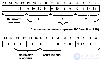
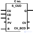
A positive edge (i.e., a change in the signal state from 0 to 1) at input S of the command Counter Forward and Down Count sets the counter to the value at input PV (Preset Value). The state of signal 1 at input R resets the counter. Resetting the counter makes the counting value equal to 0. The counter is incremented by 1 if the signal state at the CU input changes from 0 to 1 (i.e. there is a positive edge), and the counter value is less than 999. The counter decreases by 1 if the signal state at the input The CD changes from 0 to 1 (i.e. there is a positive edge), and the counter value is greater than 0. If a positive edge exists on both inputs, then both operations are performed and the counting value remains the same. Output Q is 1 if the counter is not 0.
| LAD element | Parameter | Type of data | Memory area | Description |
 | no. | COUNTER | C | An identification number timer The range depends on the CPU. |
| CU | Bool | I, Q, M, D, L | CU Direct Account Login | |
| CD | Bool | I, Q, M, D, L | CD Reverse Input | |
| S | Bool | I, Q, M, D, L | Input of the initial value | |
| PV | WORD | I, Q, M, D, L | A value from 0 to 999 to set the initial value of the counter (entered as С # <value> to designate the BCD format) | |
| R | Bool | I, Q, M, D, L | Reset input | |
| Q | Bool | I, Q, M, D, L | Counter status | |
| CV | WORD | I, Q, M, D, L | The current value of the counter (integer format) | |
| CV_BCD | WORD | I, Q, M, D, L | Current counter value (BCD format) |
Example and bits of the forward and reverse count status word
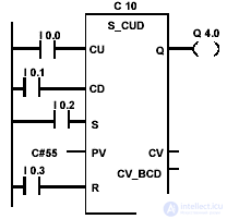 | Changing the state of the signal from 0 to 1 at input I 0.2 sets the counter C 10 to 55 in a binary-decimal format. If the state of the signal at input I 0.0 changes from 0 to 1, then the value of the counter C 10 increases by 1, except for the case when the value of the counter C 10 is 999. If the input I 0.1 changes from 0 to 1, then the counter C 10 decreases by 1 except when the value of the counter is C 10 equal to 0. If I 0.3 changes from 0 to 1, then the value of C 10 is set to 0. Q 4.0 is equal to 1 when C 10 is not equal to "0". |
| Status word bits | |||||||||
| BR | CC 1 | CC 0 | Ov | OS | OR | Sta | Rlo | FC | |
| Record | - | - | - | - | - | x | x | x | one |
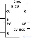
Setting the counter by the value of the input PV (Preset Value) occurs if the input S has a positive RLO front (those from 0 to 1). A positive front at the entrance of the R counter is reset. Resetting the counter makes the counting value equal to 0. With a positive front at the CU input, the counter value increases by 1 if the counting value is less than 999. Output Q is 1 if the counter is not 0. Certain restrictions are imposed on the placement of the blocks of counters (see section 1.1).
| LAD element | Parameter | Type of data | Memory area | Description |
 | no. | COUNTER | C | An identification number timer The range depends on the CPU. |
| CU | Bool | I, Q, M, D, L | CU Direct Account Login | |
| S | Bool | I, Q, M, D, L | Input of the initial value | |
| PV | WORD | I, Q, M, D, L | A value from 0 to 999 to set the initial value of the counter (entered as С # <value> to designate the BCD format) | |
| R | Bool | I, Q, M, D, L | Reset input | |
| Q | Bool | I, Q, M, D, L | Counter status | |
| CV | WORD | I, Q, M, D, L | The current value of the counter (integer format) | |
| CV_BCD | WORD | I, Q, M, D, L | Current counter value (BCD format) |
Example and bits of the word of the counter meter count status
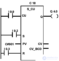 | A change in the signal state from 0 to 1 at input I 0.2 sets the counter C 10 to value 901 in binary coded decimal format. If the signal state I 0.0 changes from 0 to 1, then the value of the counter C 10 is increased by 1, if the value of C 10 is not equal to 999. If I 0.3 changes from 0 to 1, then the value of C 10 is set to 0. Signal state at the output Q 4.0 is 1 if C 10 is not 0. |
| Status word bits | |||||||||
| BR | CC 1 | CC 0 | Ov | OS | OR | Sta | Rlo | FC | |
| Record | - | - | - | - | - | x | x | x | one |
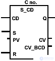
A positive edge (i.e., a change in the signal state from 0 to 1) at input S of the command. The countdown counter sets the counter to the value at input PV (Preset Value). A positive front at the entrance of the R counter is reset. Resetting the counter makes the counting value equal to 0. With a positive edge at the CD input, the counter value decreases by 1 if the counting value is greater than 0. Interrogating the signal state by 1 at the Q output gives a result equal to 1 when the counter value is greater than 0; a poll gives a result of 0 when the counter value is 0.
| LAD element | Parameter | Type of data | Memory area | Description |
 | no. | COUNTER | C | An identification number timer The range depends on the CPU. |
| CD | Bool | I, Q, M, D, L | CU reverse account entry | |
| S | Bool | I, Q, M, D, L | Input of the initial value | |
| PV | WORD | I, Q, M, D, L | A value from 0 to 999 to set the initial value of the counter (entered as С # <value> to designate the BCD format) | |
| R | Bool | I, Q, M, D, L | Reset input | |
| Q | Bool | I, Q, M, D, L | Counter status | |
| CV | WORD | I, Q, M, D, L | The current value of the counter (integer format) | |
| CV_BCD | WORD | I, Q, M, D, L | Current counter value (BCD format) |
Example and bits of the countdown counter status word
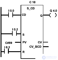 | Changing the signal state from 0 to 1 at input I 0.2 sets the counter C 10 to value 89 in binary coded decimal format. If the state of the signal at input I 0.0 changes from 0 to 1, then the value of the counter C 10 decreases by 1, unless this value is 0. The signal state at the output of Q 4.0 is 1 if the value of the counter C 10 is not 0. If I 0.3 change from 0 to 1, then the value of C 10 is set to 0. |
| Status word bits | |||||||||
| BR | CC 1 | CC 0 | Ov | OS | OR | Sta | Rlo | FC | |
| Record | - | - | - | - | - | x | x | x | one |

Comments
To leave a comment
Industrial programming. programming of controllers
Terms: Industrial programming. programming of controllers