Lecture
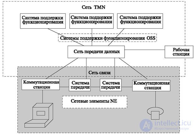
According to the concept, the management network (TMN) is separated from the communication networks and is connected to the telecommunications network via an interface. However, the concept allows the use of a telecommunications network to exchange information between TMN elements. The interconnection between the TMN and the telecommunications network is shown in Fig. 7.2. A data network is used as the network that provides communication between the NE and the OSS.

TMN may use parts of the telecommunication network to support its connections.
Such parts may be:
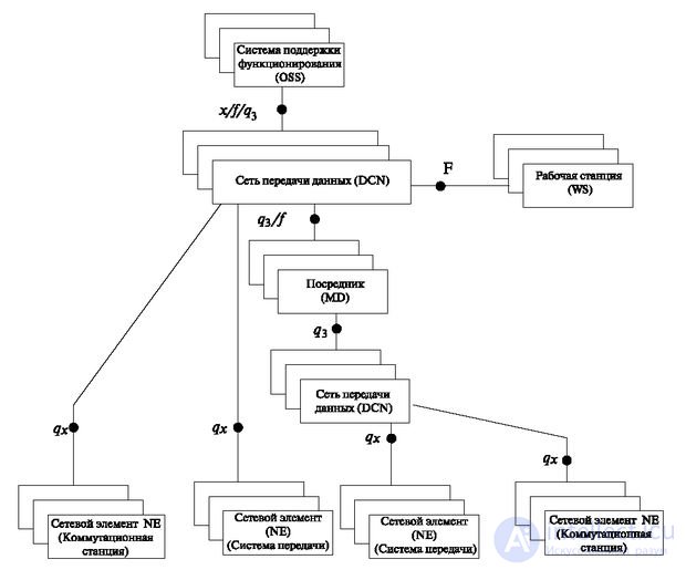
For the network shown in Fig. 7.2, defined reference points (Fig. 7.3), in which standard protocols are specified.
Fig. 7.3 differs from the previous one by the introduction of two elements - the data transmission network inside the TMN and the element "mediator" (MD - mediator).
The introduction of a second data network indicates a more general case as compared with Fig. 7.2, when the TMN network has its own data exchange network.
The mediator (intermediary) is introduced for the physical and informational coordination of the communication network and the TMN network.

According to the TMN concept, in fig. 7.3 it is possible to identify the elements on which the communication system is built (building blocks - building blocks):
The data network is not included in the number of building blocks.
The above building blocks can perform the following functions:
Each building block can perform one or more of the listed functions.
Options for the placement of these functions are shown in Table 7.2.
| Physical components | Functional blocks | ||||
|---|---|---|---|---|---|
| Nef | Mf | QAF | OSF | WSF | |
| Network Element (NE) |  |  |  |  |  |
| Mediator (MD) |  |  |  |  | |
| Q - adapter |  | ||||
| Workstation (WS) |  |  |  |  | |
| Data Network (DCN) |  | ||||
 Required accommodation Required accommodation
| |||||
For the exchange between functional blocks, the reference points are defined, at which the exchange protocols between the processes shown in Fig. 2 are specified. 7.3. Each of the reference points defined above is physically implemented as a corresponding interface.
Interface f is used to connect workstations with operation support systems and intermediaries (mediators).
Interface x - for interaction of systems with systems supporting the operation of other TMN networks.
The q interfaces provide for the interaction of network elements, operation support systems, intermediaries (mediators) and Q adapters through a data network.
The q3 interface, which is assigned a central role in TMN, serves to interface with the data transmission network of the support systems for the operation, support systems for the functioning of intermediaries in Q adapters, and network elements with built-in intermediary functions.
The q x interface is used when connecting network elements and Q adapters to an intermediary.
TMN interfaces are a formally defined set of protocols, procedures, message formats, and semantics used to transfer information using control properties within an object-oriented system. To date, the most well-developed TMN interface is q3, the details of which protocols are defined in recommendations Q.811 and Q.812.
Comments
To leave a comment
Telecommunication Services and Devices
Terms: Telecommunication Services and Devices