
Lecture
An optical neural network is a physical implementation of an artificial neural network using optical components.
Some artificial neural networks that have been implemented as optical neural networks include the Hopfield neural network and the Kohonen self-organizing map using liquid crystals.
Biological neural networks operate on an electrochemical basis, whereas optical neural networks use electromagnetic waves. Optical interfaces to biological neural networks can be created using optogenetics, but this is not the same thing as optical neural networks. In biological neural networks there are many different mechanisms for dynamically changing the state of neurons, including short-term and long-term synaptic plasticity. Synaptic plasticity is one of the electrophysiological phenomena used to control the efficacy of synaptic transmission - long-term plasticity for learning and memory, and short-term plasticity for brief, transient changes in synaptic transmission efficacy. Implementing this using optical components is difficult, and ideally requires advanced photonic materials. Properties that may be desirable in photonic materials for optical neural networks include the ability to change their light-transmission efficiency depending on the intensity of the incoming light.
Holographic correlators store exemplar images as either a planar or a volume hologram and recover them under coherent illumination. An input image, which may be noisy or incomplete, is fed into the system and simultaneously correlated optically with all the stored exemplar images. These correlations are processed by a thresholding function and fed back into the system’s input, where the strongest correlations reinforce the input image. The reinforced image passes through the system repeatedly, changing with each pass until the system stabilizes on the required image.
Thus, such devices are physical analogs of the Hopfield neural network, the Kosko neural network, and many others.
1. Operating principle of the holographic correlator
A typical layout implementing the optical matched-filtering method based on a holographic filter, known as a holographic correlator, is shown in Fig. 1. Its operating principle is based on comparing the input image with a reference one. In the context of inspection, the decision on the quality of the part being inspected is made here based on the magnitude of the correlator’s output signal, described mathematically by the expression [4,5]
 , (1)
, (1)
where  — a variable parameter characterizing the state of the part being inspected;
  — coordinates of the filtering plane;
  - amplitude transmittance of the input plane with the reference part;
  — amplitude transmittance of the input plane with the part being inspected;
  — the correlation operation symbol.
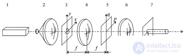
Fig. 1. Diagram of the holographic correlator, where:
1 - laser, 2 - collimator, 3 - input plane, 4 and 6 - optical Fourier-transform systems, 5 - holographic filter, 7 - output plane.
A distinctive feature of the layout under consideration is that the output signal, the cross-correlation function (CCF) (1), is computed not in the object (input) plane, but in the frequency plane. To this end, the part being inspected is placed in the input plane 3 and illuminated by a plane light wave formed by collimator 2 from the radiation of laser 1. The light passing through the input plane reaches optical system 4, in whose back focal plane the Fourier spectrum  is formed, where
  — coordinates of the input plane;
  — amplitude transmittance of the input plane with the part being inspected;
  and
and  — spatial frequencies;
  — wavelength of the laser radiation;
  - focal length of the optical system. Also located here is holographic filter 5, whose transfer characteristic is complex-conjugate to the Fourier spectrum
  , where
  — amplitude transmittance of the input plane with the reference part. At the filter output, the light distribution is the result of multiplying the Fourier spectrum of the part being inspected by the filter’s transfer characteristic, i.e.,
  , where
  — the complex-conjugation operation symbol. After the resulting light distribution passes through optical system 6, which performs the inverse Fourier transform, a correlation response is formed in its back focal plane in accordance with expression (1). The correlation response takes the form of a bright light spot whose intensity is equal to
  . The intensity of the correlation spot is converted by photodetector 7 into an electrical signal, which is analyzed by electronic means, and based on the results of the analysis a decision is made on the quality of the part being inspected. When deciding on the quality of the part being inspected, an estimate is made of the relative intensity in the correlation response, determined by the relation
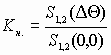 , (2)
, (2)
where  — intensity of the correlation response at point
  .
.
Thus, it follows from the correlator’s operating algorithm that, in order to establish its metrological capabilities and the requirements for the orientation of parts at the inspection position, it is necessary to study the dependence of the cross-correlation function (1) on the factors mentioned.
HOLOGRAPHIC PATTERN RECOGNITION, the recognition of an object’s image by methods of holography and coherent optics, consisting in comparing the image of the object being recognized with its reference image, known in advance. The measure of similarity between the object’s image and the reference is their cross-correlation function (CCF). The task of holographic pattern recognition consists in establishing the presence of the object being recognized in the image under analysis and determining its coordinates within the field of view of the recognition system. To do this, the CCF of the pattern being recognized and its reference is computed, and the maximum of this function is compared with a threshold value determined by the probability of correct recognition. If the correlation signal exceeds the threshold, the object is detected; if the correlation signal is below the threshold, the object is not present in the image under analysis. At the same time, the object’s coordinates are determined from the position of the maximum of the correlation function.
Holographic pattern recognition is carried out in the Vander Lugt holographic correlator and the joint transform correlator. Both correlators use an optical spatial image-filtering system, in whose frequency plane a holographic matched filter (HMF) is installed, in the form of a Fourier hologram of the pattern being recognized or a generalized Fourier hologram. The operation of the correlator is based on the property of a lens to perform a two-dimensional Fourier transform of an image under coherent illumination (see Fourier optics). The CCF is synthesized in the frequency plane of the correlator by comparing the spatial-frequency spectra of the pattern being recognized and the reference pattern recorded as a hologram.
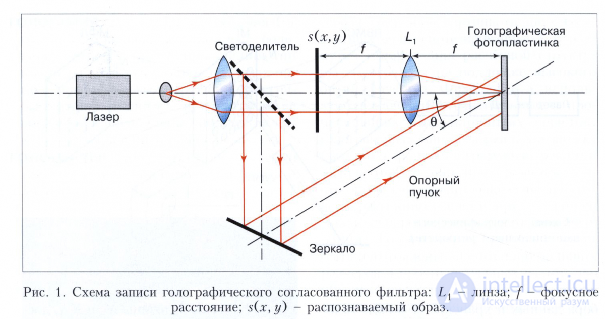
The recognition process consists of two stages: in the first, a holographic matched filter is made for the pattern to be recognized (the reference), and in the second, the actual recognition is carried out. When making the filter (Fig. 1), a transparency recording the pattern to be recognized s(x,y) is placed in the front focal plane of lens L1, while a holographic photographic plate is placed in the back focal plane, onto which a reference beam is directed at an angle θ to the optical axis. After exposure and photochemical processing, the resulting filter is placed in plane P2 (Fig. 2), precisely at the location where the photographic plate was during its recording, while in plane P1 a transparency is placed recording the image under analysis g(x, y) = s(x, y) + n(x, y), which contains not only the pattern to be recognized s(x, y) but also the images of other objects n(x, y). Lens L1 forms, in plane P2, the spatial-frequency spectrum S(vx,vy) + N(vx,vy) of the image under analysis, where S(vx,vy) is the Fourier transform of the image to be recognized, N(vx,vy) is the Fourier transform of the other objects, and vx, vy are the spatial frequencies along the x and y axes, respectively.
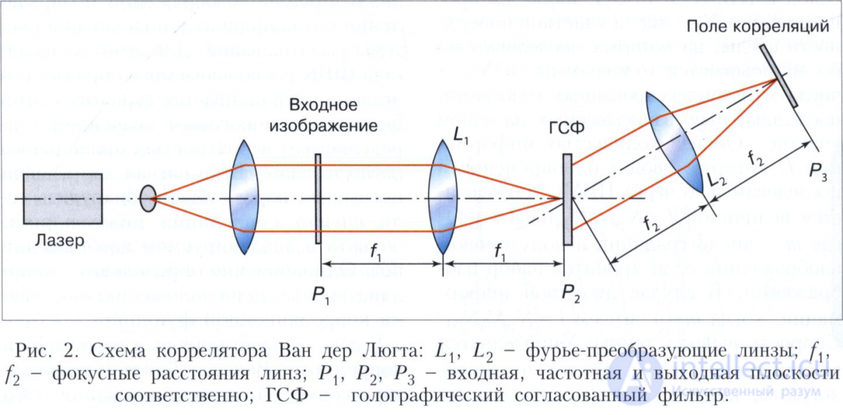
As a result of the diffraction of the spatial-frequency spectrum on the holographic matched filter, three diffracted beams are formed: the zero order and the ± 1st orders. The +1st-order beam, propagating in the direction of the reference beam used when recording the filter, after passing through lens L2 forms, in plane P3, the correlation field between the reference image of the object and the images of other objects in the analyzed image, while the -1st-order beam forms, in plane P3, the convolution region of these images. The angle θ is chosen so that the correlation and convolution fields do not overlap with the zero-order region. At the location of the pattern being recognized, an autocorrelation function is formed in the shape of a bright focused spot 50-100 µm in size, while at the locations of other objects a cross-correlation function is formed in the shape of defocused spots of larger size and lower intensity. Fig. 3 illustrates the process of recognizing a specific Chinese character among others.
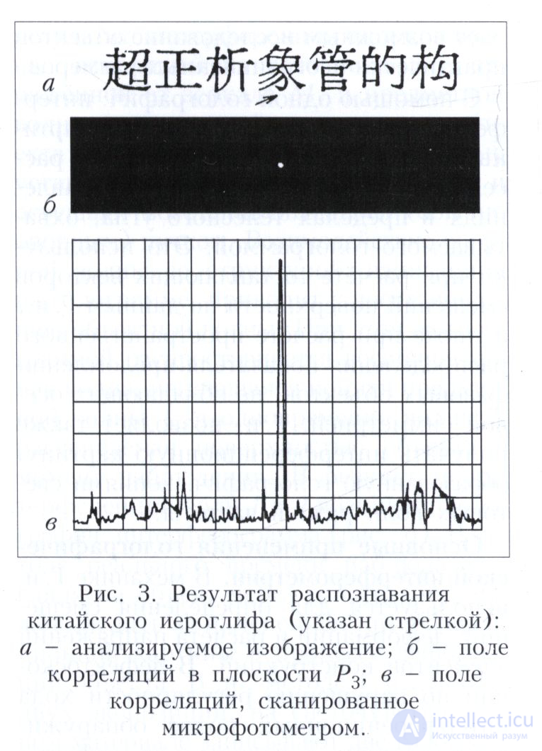
In practice, instead of photographic transparencies and holographic plates, controllable transparencies with optical and electrical addressing are used, as well as photorefractive crystals and photopolymers.
The advantage of holographic pattern recognition is the speed of computing the two-dimensional cross-correlation function (nanoseconds) and the independence of the recognition time from the dimensionality of the image under analysis and the pattern being recognized. The drawback is the dependence of the correlation signal intensity on misalignment with the reference in angle and size. Depending on the complexity of the pattern being recognized, a misalignment of 2-3° in angle and 5-10% in size leads to a twofold decrease in the correlation signal. Holographic pattern recognition is used in identifying fingerprints, faces, credit cards, characters, parts on a conveyor during automated assembly, ground landmarks in navigation systems, and the like.
With the development of nanophotonics, it has become possible to use bacteriorhodopsin-containing films as the primary material for fabricating optical neural networks. The protein bacteriorhodopsin is close in function and structure to visual rhodopsin. Thus, an artificial retina built on this basis would most closely correspond to the physiological prototype. But bacteriorhodopsin can be used to build not only an artificial retina but also a formal neuron. This makes it possible, in principle, to implement any type of modern artificial neural network based on membranes containing the bacteriorhodopsin protein.
It should be noted that bacteriorhodopsin is not the only protein used for these purposes. Also promising for research is the photoactive yellow protein PYP (photoactive yellow protein), a receptor protein found, for example, in the organism Ectothiorhodospira halophila. This protein provides negative phototaxis in bacteria - moving away from light.
In 2007, a model of optical neural network appeared: the Programmable Optical Array/Analog Computer (POAC). It was implemented in 2000 and was based on a modified joint transform correlator (JTC) and bacteriorhodopsin (BR) as a holographic optical memory. Full parallelism, large array size, and the speed of light are the three promises offered by POAC for implementing an optical CNN. These have been investigated in recent years, taking into account their practical limitations and considerations, resulting in the development of the first portable version of POAC.
Practical details - hardware (optical circuits) and software (optical templates) - have been published. However, POAC is a universal programmable array computer that has a wide range of applications, including:
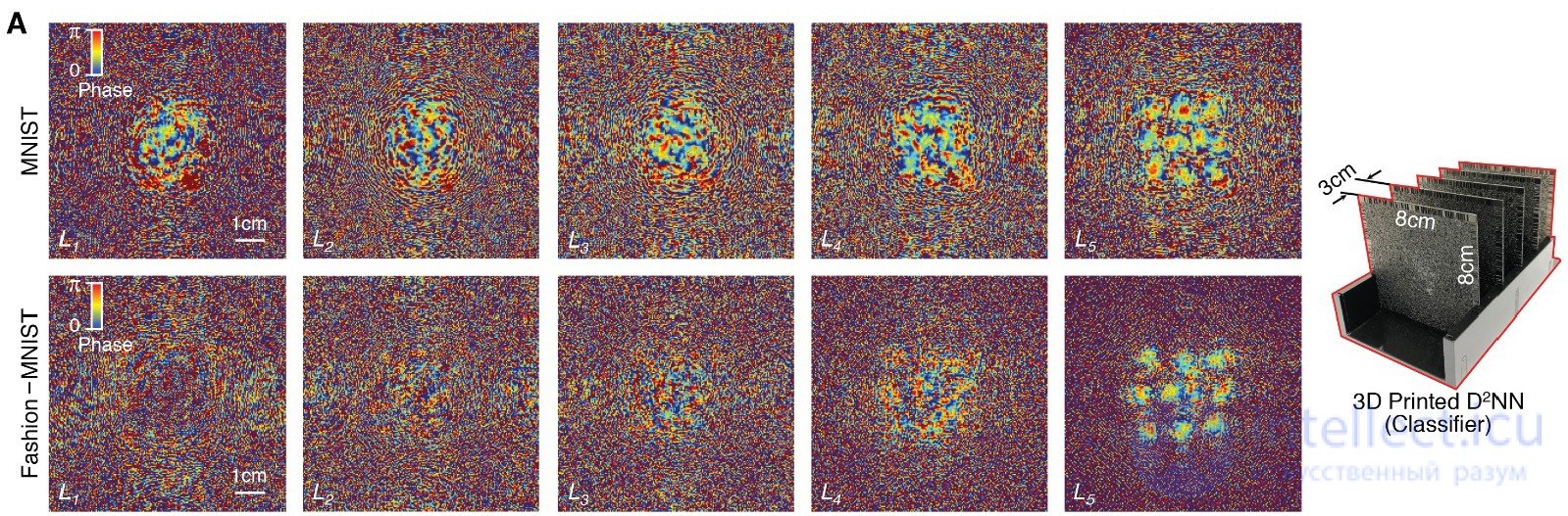
A trained multilayer phase mask (handwritten-character classifier). On the right is a physical model of the D²NN optical neural network, 3D-printed: layers 8×8 cm in size, spaced 3 cm apart
A group of researchers from the University of California, Los Angeles has developed a new type of neural network that uses light instead of electricity in its operation. The journal Science has published an article describing the idea, the working device, its performance, and the types of applications that, in the authors’ opinion, are well suited to being computed on this new type of neural network.
The fully optical deep learning framework Diffractive Deep Neural Network (D²NN) is physically formed from a large number of reflective or transparent surfaces. These surfaces work together to perform an arbitrary function learned through training. While obtaining the result and making predictions in the physical network are organized entirely optically, the training part, involving the design of the structure of the reflective surfaces, is computed on a computer.
So, physically, the D²NN model consists of several reflective or transparent layers. On these layers, each point either transmits or reflects the incoming wave. Thus, this point represents an artificial neuron, which is connected to the neurons of the following layers via optical diffraction. The structure of D²NN is shown in the illustration.
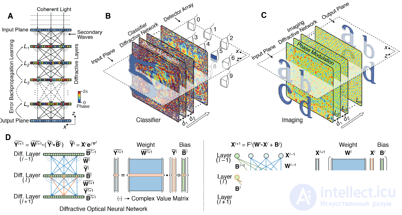
Diffractive Deep Neural Network (D²NN).
In illustration A — a diagram of several transparent/reflective layers, where each point represents a neuron with a complex transmission or reflection coefficient. These coefficients are derived through deep learning. After the training phase, the design of the D²NN is fixed — and the corresponding plates, which perform computation according to the function obtained from the prior training, are 3D-printed. Unlike electronic computer networks, computation here is carried out at the speed of light.
In the course of the experiments, the scientists trained and experimentally tested several types of D²NN. Illustration B shows a handwritten-character classifier, illustration C — a lens (imaging lens).
The lower part of the illustration compares the operation of the diffractive optical neural network (left) and the electronic neural network (right). Being based on coherent waves, D²NN operates with complex-valued inputs and a multiplicative bias. The weights in D²NN are based on free-space diffraction and determine the coherent interference of secondary waves, which are phase- and/or amplitude-modulated by the preceding layers. The symbol "ο" denotes the Hadamard product operation, that is, the element-wise multiplication of the corresponding entries of two sequences of equal length.
The researchers explain that the structure of the optical neural network is organized according to Huygens’ principle, according to which each element of the wavefront can be regarded as the center of a secondary disturbance generating secondary spherical waves, and the resulting light field at each point in space is determined by the interference of these waves. Thus, an artificial neuron in D²NN is connected to other neurons of the following layer via a secondary wave, which is modulated in amplitude and phase both by the input interference pattern created by the earlier layers and by the local transmission/reflection coefficient at that point.
By analogy with standard deep neural networks, the transmission/reflection coefficient of each point/neuron can be regarded as a multiplicative «bias» term, which is iteratively adjusted during the training of the diffractive network using the backpropagation method. After numerical training, the design of the D2NN is fixed and the transmission/reflection coefficients of the neurons in all layers are determined. The calculated layers can then be fabricated by any method: 3D printing, lithography, etc.
The scientists emphasize that the optical neural network performs its function at the speed of light and requires no energy. Thus, it represents an efficient and fast way of implementing machine learning tasks.
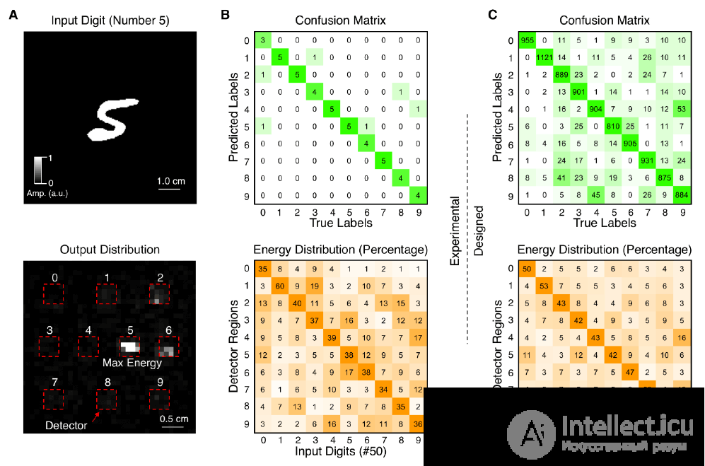
To test the idea, the researchers built a neural network capable of recognizing digits from zero to nine — and reporting the result. After training on 55,000 images of numbers, the printed seven-layer neural network showed an accuracy of 93.39%.
In recognizing fashion clothing and footwear, the five-layer neural network showed an accuracy of 81.13%, and the ten-layer network — 86.60%.
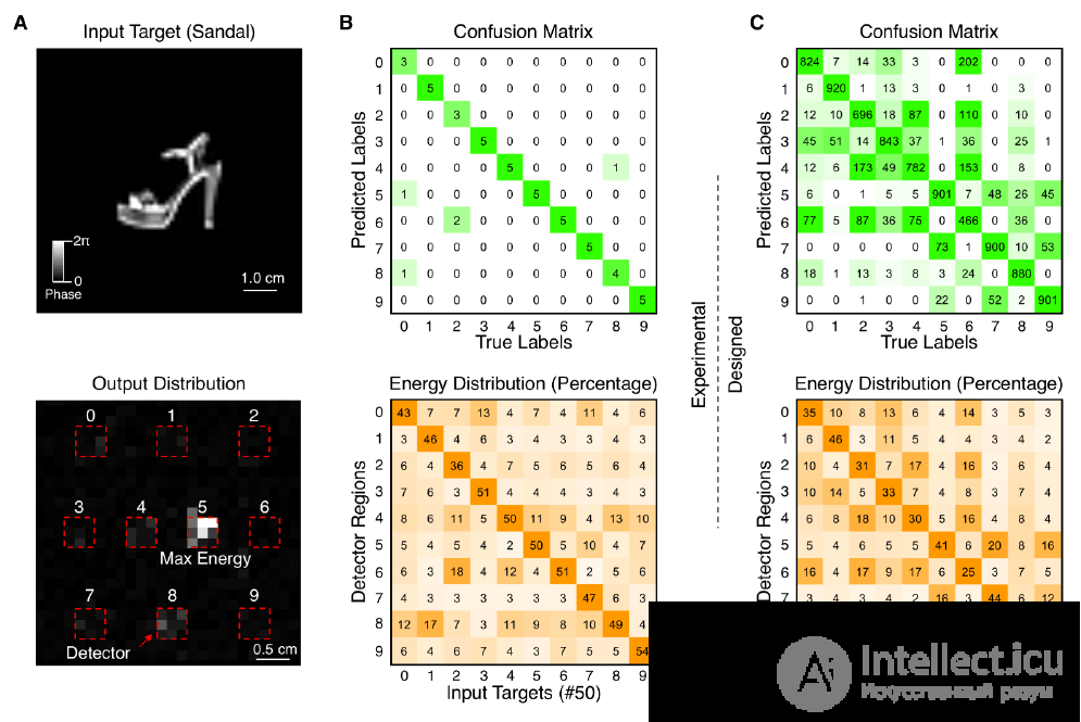
In the researchers’ opinion, an optical-type neural network can be used in specialized devices requiring high speed, such as identifying a specific face in a crowd of moving people.
1 Scientific article published July 26, 2018 in the journal Science (doi: 10.1126/science.aat8084).
2 Goodman J. Introduction to Fourier Optics. Moscow, 1970; Vasilenko G. I. Holographic Pattern Recognition. Moscow, 1977; Applications of Fourier Optics Methods / Edited by H. Stark. Moscow, 1988.

Comments