Lecture
The reaction of an automaton is the sequence of output signals of an automaton obtained under the influence of a certain sequence of input signals, that is, the reaction is the output word of the automaton to a specific input word.
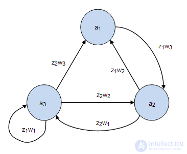
So for an automaton in Figure 2.1, the formation of the reaction is presented in Table 2.1. The input of the machine is a sequence of input signals.  . The automaton is in the initial state
  . Incoming input signal
  puts the machine in state
  and the output signal is formed on this transition at the same discrete moment of time.
  . In the second moment of time
  an input signal acts on the machine
  which translates the machine to the state
  , and on this transition at the same discrete point in time
  output signal is generated
  and so on. As a result, the input word
  formed output word
  which is the reaction of the automaton.
| Time t | t1 | t2 | t3 | t4 | t5 | |
|---|---|---|---|---|---|---|
| Input signals | z 1 | z 2 | z 1 | z 2 | z 2 | |
| States | a 1 | a 2 | a 3 | a 3 | a 2 | a 1 |
| Output signals | w 3 | w 1 | w 1 | w 2 | w 2 |
For Moore's automaton, the formation of a reaction occurs in a similar way, with the only difference that in Moore’s automaton, the output signal is not given at the transition of the automaton from the state  in state
  as in the Miles automaton, and after the automaton passed into the state
  .
.
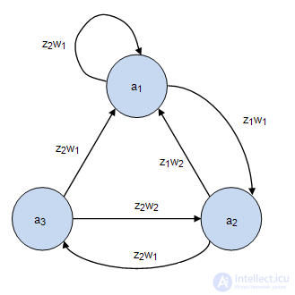
Automatic Miles  Fig.2.2 is set to its original state
  .An input is the input word:
  . As a result, the output word is formed.
  which is the reaction of the automaton (Table 2.2). Moore's gun
  the graph, which is presented in Fig.2.3, is set to its original state
  .
.
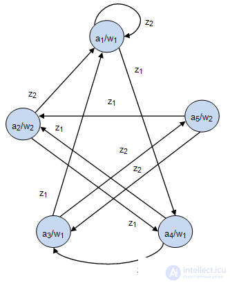
The input is the same input word:  . As a result, the output word is formed.
  which is the reaction of the automaton (Table 2.3).
| Moments of time | t1 | t2 | t3 | t4 | t5 | t6 | t7 |
|---|---|---|---|---|---|---|---|
| Input word | z1 | z1 | z2 | z1 | z2 | z2 | |
| States | a1 | a2 | a1 | a1 | a2 | a3 | a2 |
| Output word | w1 | w2 | w1 | w1 | w1 | w2 | |
| automatic reaction | |||||||
| Moments of time | t1 | t2 | t3 | t4 | t5 | t6 | t7 |
|---|---|---|---|---|---|---|---|
| Input word | z1 | z1 | z2 | z1 | z2 | z2 | |
| States | a1 | a4 | a2 | a1 | a4 | a3 | a5 |
| Output word | w1 | w1 | w2 | w1 | w1 | w1 | w2 |
| automatic reaction | |||||||
Two automatic  and
and  are called equivalent if:
There is a theorem: for any Moore machine gun, there is an equivalent Mealy machine gun and vice versa.
In the tabular task, the transition table of the Mile automaton coincides with the transition table of the Moore automaton. The exit table of the Miles machine is obtained from the transition table by replacing the symbol  standing at the line crossing
  and column
  per character
  marking the column
  in the combined table of Moore’s machine gun.
Let Moore's automaton be given (Table 2.4). The transition table of the equivalent Mile automaton (Table 2.5) coincides with the combined Moore automaton table representing the automaton transitions, and the output table 2.6 is obtained as follows. It is believed that on the transition from the state  in state
  in the equivalent Miles machine, the same output signal should be generated as in the Moore machine, after the state machine went into
  i.e. output signal
  .
.
| w1 | w2 | w3 | w2 | w3 | |
|---|---|---|---|---|---|
| a1 | a2 | a3 | a4 | a5 | |
| z1 | a2 | a5 | a5 | a3 | a3 |
| z2 | a4 | a2 | a2 | a1 | a1 |
| a1 | a2 | a3 | a4 | a5 | |
|---|---|---|---|---|---|
| z1 | a2 | a5 | a5 | a3 | a3 |
| z2 | a4 | a2 | a2 | a1 | a1 |
| a1 | a2 | a3 | a4 | a5 | |
|---|---|---|---|---|---|
| z1 | w2 | w3 | w3 | w3 | w3 |
| z2 | w2 | w2 | w2 | w1 | w1 |
Consider the transition of the automaton from the state  in state
  . In Moore's machine as
  matches the output signal
  , therefore in table.2.6 at the transition from the state
  on input signal
  set
set  and so on.
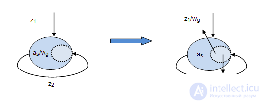
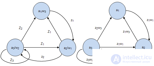
In the graphic task of Moore’s automaton, the transition to the Mile’s automaton is performed as follows: output signal  being molded into
  , is transferred to all the arcs entering this vertex, a graphical interpretation of this is shown in Figure 2.4, and an example of the transformation of the Moore machine gun into the equivalent Mealy machine is shown in Fig. 2.5.
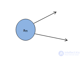
Restriction: In the Mile machine there should be no transition states, i.e. States in which there is at least one outgoing arc and there is not a single incoming arc, as shown in Fig. 2.6.
In Moore's automaton, the output signal  formed as a function
  , and in the Miles machine -
  . And
. And  - the current state of the machine,
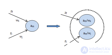
  - the previous state of the machine. Thus, the state
  corresponds to a group
  whose number is equal to the number of different output signals
  located on incoming arcs. A graphic interpretation of this is shown in Figure 2.7.
Let the Mile machine gun be given:  . I want to go to the equivalent Moore machine
  , that is, you need to build such an Moore automaton:
  , what
  and
and  . Consider an example. Dan machine Miles Fig.2.8-2.9. We construct the set of states of the automaton.
  . For this we find the pair:
 ;
;
 ;
;
 ;
;
 .
.
Redesigning  accordingly as
  , we get the graph shown in Figure 2.8-2.9.
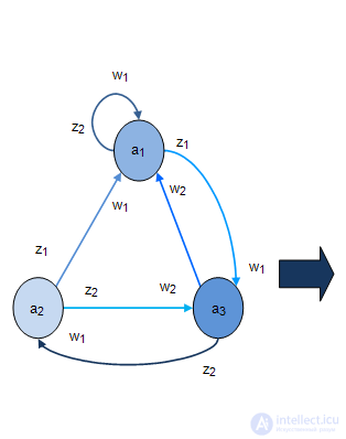 Fig. 2.8. | 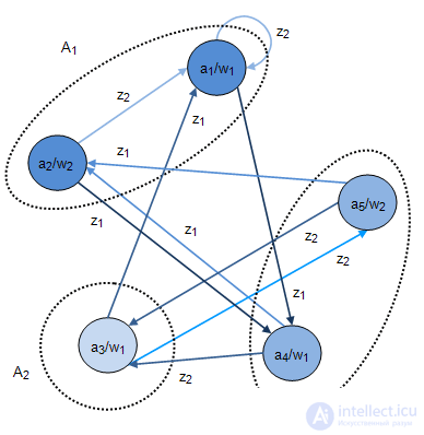 Fig. 2.8. |
Comments
To leave a comment
Theory of Automata
Terms: Theory of Automata