
Lecture
Let us consider the specific features of the discrete-deterministic approach at the stage of formalising the operating process of systems, using automata theory as the mathematical apparatus. Automata theory is a branch of theoretical cybernetics that studies mathematical models — automata. On the basis of this theory, the system is represented in
the form of an automaton that processes discrete information and changes
its internal states only at permissible instants of time. The concept of an
«automaton» varies depending on the nature of the specific systems under study, the adopted level of abstraction, and the appropriate degree of generality.
An automaton can be represented as a device (a black box),
to which input signals are supplied and from which output signals are taken, and which may
have a number of internal states. A finite automaton is an automaton whose set of internal states and input signals (and,
consequently, its set of output signals) are finite sets.
Abstractly, a finite automaton (finite automata) can be represented
as a mathematical scheme (an F-scheme) characterised by six elements:
a finite set X of input signals (the input alphabet); a finite
set Y of output signals (the output alphabet); a finite set Z of internal states (the internal alphabet, or the alphabet of states); an initial state
z0 ∈ Z
; a transition function
φ(z, x)
; and an output function
ψ(z, x). The automaton defined by the F-scheme
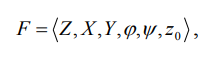
– operates in discrete automaton time, whose instants are clock
cycles, that is, contiguous equal intervals of time, each of
which corresponds to constant values of the input and output
signals and of the internal states. Let us denote the
state, and also the input and output signals, corresponding
to the t-th clock cycle for t = 0,
1, 2, ..., by zt, xt, yt. Here z0
= z⁰, zt ∈ Z, xt ∈ X, yt
∈ Y. An abstract finite automaton has one input
channel and one output channel. At every instant t
= 0, 1, 2, ... of discrete time the
F-automaton is in a definite state zt; at the
initial instant t = 0 it is always in
the initial state z0 = z⁰. At instant t,
being in state zt, the automaton is able to
receive a signal xt ∈ X on its input
channel and to produce, on its output channel, a
signal yt = ψ(zt, xt), passing into state zt+1
= φ(zt, xt), zt ∈ Z, yt ∈ Y.
The abstract finite automaton realises a certain mapping of
the set of words of the input alphabet X
onto the set of words of the output alphabet
Y. In other words, if the finite automaton, set
to its initial state z0, is fed, in some
sequence, with letters of the input alphabet x0, x1,
x2, ..., that is, an input word, then letters
of the output alphabet y0, y1, y2, ..., will
successively appear at the output of the automaton, forming
an output word. Thus, the operation of the finite
automaton follows the scheme below: at each t-th clock
cycle a certain signal xt is fed to the
input of the automaton, which is in state zt,
and the automaton reacts to it by passing, in
the (t+1)-th clock cycle, into a new state zt+1
and producing a certain output signal. The above can
be described by the following equations: for an F-automaton
of the first kind, also called a Mealy automaton,
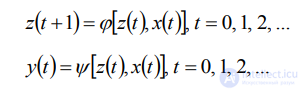
(10)
(11)
for an automaton of the second kind


An automaton of the second kind, for which yt = ψ(zt), t
= 0, 1, 2, ... (14), that is, whose output function does
not depend on the input variable xt, is called a Moore automaton.
Thus, equations (10) — (14), which fully define the F-automaton, are a
particular case of equations (3) – (4), when the system S is
deterministic and a discrete signal X arrives at its single input. By
the number of states, finite automata are divided into automata with memory
and automata without memory. Automata with memory have more than one state,
and those without – only one state. By the manner in which
discrete time is reckoned, finite automata are divided into synchronous and asynchronous
ones. In synchronous F-automata, the instants of time at which the automaton
«reads» the input signals are forced by synchronising signals. After each successive
synchronising signal, taking into account the value «read» and in accordance with
equations (10) — (14), a transition to a new state and the
issuing of an output signal take place, after which the automaton can
accept the next value of the input signal. Thus, the automaton's reaction
to each value of the input signal is completed within one clock
cycle, whose duration is determined by the interval between neighbouring synchronising signals.
An asynchronous F-automaton reads the input signal continuously, and therefore, reacting to
a sufficiently long input signal of constant value x, it may change
state several times, issuing a corresponding number of output signals, until it
passes into a stable state that can no longer be changed by
that input signal. To define a finite F-automaton, it is necessary
to describe all the elements of the set F = ⟨Z,
X, Y, φ, ψ, z0⟩, that is, the input, internal and
output alphabets, as well as the transition and output functions, and
among the set of states the state z0 in which the
automaton was found at the instant t = 0 must be
singled out. There are several ways of specifying the operation of
F-automata, but the tabular, graphical and matrix methods are the ones
most often used. The simplest tabular method of specifying a finite
automaton is based on the use of transition and output tables,
whose rows correspond to the input signals of the automaton, and
whose columns — to its states. Here, the leftmost column usually
corresponds to the initial state z0. At the intersection of the
i-th row and the k-th column of the transition table is
placed the corresponding value φ(zi, xk) of the transition function, while
in the output table — the corresponding value ψ(zi, xk) of
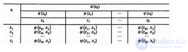
the output function. For a Moore F-automaton the two tables can
be combined, giving what is known as a marked transition table,
in which, above each state zk of the automaton denoting a
column of the table, there stands the output signal ψ(zk) corresponding
to that state, according to (14). The operation of the Mealy
F-automaton, described by the transition table φ and the output table
ψ, is illustrated in Table 1, while the operation of the
Moore F-automaton is described by a transition table — Table 2.
Table 1. Description of the operation of the Mealy F-automaton
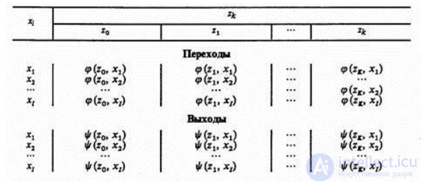
Table 2. Description of the operation of the Moore F-automaton
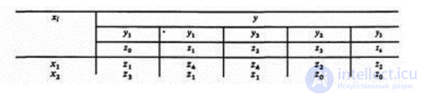
Example. The Mealy F-automaton F1 with three states, two input and
two output signals is given in Table 3, and the Moore F-automaton F2 — in Table 4.
Table 3. Mealy F-automaton F1
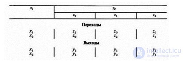
Table 4. Moore F-automaton F2
Another way of specifying a finite
automaton uses the concept of a
directed graph. The graph of an
automaton is a set of vertices,
corresponding to the different states of
the automaton, and arcs joining the
vertices, corresponding to the various transitions
of the automaton. If an input
signal xk causes a transition from
state zi to state zj, then
on the graph of the automaton
the arc joining vertex zi to
vertex zj is labelled xk. In
order to specify the output function,
the arcs of the graph must
be marked with the corresponding output
signals. For Mealy automata this marking
is done as follows: if
an input signal xk acts
on state zi, then, as
stated above, an arc results,
originating from zi and labelled
xk; this arc is additionally
marked with the output signal
yi = ψ(zi, xk). For
a Moore automaton the analogous
marking of the graph is
as follows: if an input
signal xk, acting on some
state of the automaton, causes
a transition to state zj,
then the arc directed into
zj and labelled xk is
additionally marked with the output
signal yj = ψ(zj, xk).
Figure 4 shows the Mealy
F-automaton F1 (a) and the
Moore F-automaton F2 (b), previously
specified by tables. In solving
problems of system modelling, a
more convenient form is often
the matrix specification of a
finite automaton. Here the connection
matrix of the automaton is
a square matrix C =
‖cij‖, whose rows correspond to
the states of origin, and
whose columns – to the
states of transition. The element
cij = xk/ys, standing at
the intersection of the i-th
row and the j-th column,
corresponds, in the case of
a Mealy automaton, to the
input signal xk that causes
the transition from state zi
to state zj, and to
the output signal ys issued
during that transition. If the
transition from state zi to
state zj occurs under the
action of several signals, the
element cij of the matrix
is a set of «input-output»
pairs for that transition, joined
by the disjunction sign. For
a Moore F-automaton the element
cij is equal to the
set of input signals on
the transition zi and zj,
while the output is described
by the output vector y
= ‖ψ(z0), ψ(z1), ..., ψ(zK)‖.
It should be noted that
in practice automata are in
general always asynchronous, and the
stability of their states is
ensured, for example, by the
introduction of synchronising signals. However,
at the level of the
abstract theory, when a finite
automaton serves as a mathematical
scheme for formalising specific objects
without taking into account a
number of secondary features, it
proves convenient to operate with
synchronous finite automata. Thus, the
concept of an F-automaton in
the discrete-deterministic approach to the
study of the properties of
objects on models is a
mathematical abstraction convenient for describing
a wide class of operating
processes of real objects in
automated information-processing and control systems.
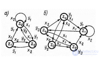
Fig. 4. Mealy and Moore F-automata, respectively
In the first place, among such objects one should mention the elements and units of computers, monitoring, regulation and control devices, and systems of
temporal and spatial switching in information-exchange technology, and so on. All the objects listed are characterised by the presence of discrete states and a
discrete character of operation in time, that is, their description by means of F-schemes is effective. But the breadth of their application does not
mean that these mathematical schemes are universal. For example, this approach is unsuitable for describing decision-making processes, or processes in dynamic systems containing transient
processes and stochastic elements. Let us consider the features of constructing mathematical schemes under the discrete-stochastic approach to formalising the operating process of the
system S under study. Since the essence of time discretisation in this approach remains analogous to that of finite automata, we shall trace the
influence of the stochasticity factor also on a variety of such automata, namely on probabilistic (stochastic) automata. In general form, a probabilistic automaton (probabilistic
automat) can be defined as a discrete, clock-cycle-by-clock-cycle transducer of information with memory, whose operation at each clock cycle depends only on the state
of its memory and can be described statistically. The use of schemes of probabilistic automata (P-schemes) is of great importance for developing methods of
designing discrete systems that exhibit statistically regular random behaviour, for elucidating the algorithmic capabilities of such systems and substantiating the limits of the
appropriateness of their use, and also for solving problems of synthesising, according to a chosen criterion, discrete stochastic systems that satisfy given constraints.
Let us introduce the mathematical
concept of a P-automaton, using
the concepts introduced for the
F-automaton. Consider a set G
whose elements are all possible
pairs (xi, zs). If there
exist two such functions φ
and ψ by means of
which the mappings G→Z and
G→Y are carried out, then
we say that F =
⟨Z, X, Y, φ, ψ⟩
defines an automaton of deterministic
type. Let us introduce a
more general mathematical scheme. Let
Φ be the set of
all possible pairs of the
form (zk, yj). Let us
require that every element of
the set G induce on
the set Φ a certain
distribution law with probabilities bkj
of the automaton passing into
state zk and of a
signal yj appearing at the
output, given that it was
in state zs and the
signal xi arrived at its
input. In this case it
holds that the sum, over
k = 1..K and j
= 1..J, of bkj equals
1. The number of such
distributions equals the number of
elements of the set G.
Let us denote the set
of these tables by B.
Then the quadruple of elements
F = ⟨Z, X, Y,
B⟩ is called a probabilistic
automaton (P-automaton). Suppose the elements
of the set G induce
certain distribution laws on the
subsets Y and Z, for
which the sum, over k
= 1..K, of z_k equals
1, and the sum, over
k = 1..J, of qk
equals 1, where z_k, qk
– are the probabilities of
the P-automaton passing into state
zk and of the output
signal yk appearing, given that
the P-automaton was in state
zs and the input signal
xi arrived at its input.
If, for all k and
j, the relation bkj =
qk·z_j holds, then such a
P-automaton is called a probabilistic
Mealy automaton. This requirement means
that the condition of independence
of the distributions for the
new state of the P-automaton
and for its output signal
is satisfied. Suppose now that
the determination of the output
signal of the P-automaton
depends only on the
state in which the
automaton is at the
given clock cycle. In
other words, suppose that
every element of the
output subset Y induc
es a probability distribution of the outputs,
for which the sum, over i =
1..I, of s_i equals 1, s_i –
being the probability of the output signal
yi appearing, given that the automaton was
in state zk. If, for all k
and i, the relation bki = z_k·s_i
holds, then such a P-automaton is called
a probabilistic Moore automaton. The concept of
P-automata of the Mealy and Moore
types is introduced by analogy with
the deterministic F-automaton, defined as F
= ⟨Z, X, Y, φ, ψ⟩.
A particular case of the P-automaton,
defined as F = ⟨Z, X,
Y, B⟩, is formed by automata
in which either the transition to
a new state or the output
signal is determined deterministically. If the
output signal of the P-automaton is
determined deterministically, such an automaton is
called a Y-deterministic probabilistic automaton. Similarly,
a P-automaton in which the choice
of the new state is deterministic
is called a Z-deterministic probabilistic automaton.

Comments