Lecture
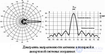
The most complete picture of the directional properties of the antenna gives a radiation pattern. This is a graph showing the dependence of antenna gain on direction. The direction changes in three-dimensional space, therefore in reality the radiation pattern is a three-dimensional body. But with satellite antennas, with very few exceptions, it is symmetrical about its axis, that is, it is a body of rotation. Therefore, a completely flat image is enough - a cross section of a radiation pattern in a plane (for example, horizontal), the coordinate pattern is more vivid, and in a Cartesian coordinate system it is more convenient. The specifications of satellite antennas for individual reception of the radiation pattern are not given, but the characteristics directly related to its specific points are indicated.
Gain , or directional gain (KND), shows how many times the power of the useful signal at the antenna output is greater than the power of the same signal when received at the omnidirectional antenna. For a parabolic antenna, the gain is calculated by the formula:
G = h * (nD / A) ^ 2
Where: G - gain;
h is the efficiency or utilization rate of the antenna surface (IEE), for most antennas is approximately 0.55;
D is the diameter of the antenna;
A is the wavelength;
n - PI.
The formula shows that the antenna gain is different for different wavelengths. Therefore, the gain of the same antenna in the C and in the Ki-bands is different. The gain of satellite dishes is tremendous. For example, an antenna with a diameter of 90 cm at frequencies of the C band (wavelength of about 2.5 cm) has a gain of about 8000. For comparison: conventional television antennas usually have a gain of 2 to 20. For convenience, the gain of satellite antennas is indicated in specifications in logarithmic units - decibels: G (AB) = 10 log G
For example, the gain of the same antenna 90 cm in decibels will be equal to 10log (8000) = 39 dB. Logarithmic units are more convenient for recording and calculating, however, people who are not experienced in mathematics are often misled. The fact is that the multiplication of absolute values is equivalent to the addition of these values in decibels. For example, the number 2 corresponds to 3 decibels. Accordingly, the gain of 8000 * 2 = 16000 in decibels will be equal to 39 dB + 3 dB = 42 dB. Therefore, the question sometimes arises: why two antennas differ greatly in size, and their gain is expressed by such “close” numbers. In fact, a difference of only 3 dB corresponds to a difference of 2 times, a difference of 6 dB is 4 times, and so on.
Gain - the most important parameter of the antenna, however, choosing the antenna according to the specification, you should not even pay attention to it. The fact is that none of the manufacturers of antennas for individual reception does not measure the real gains. The gain specified in the specification is calculated using the formula given above for the diameter and wavelength. Other factors, first of all - the quality of production, while not taken into account, and the coefficient h each manufacturer chooses "by eye" (or rather, as conscience allows) in the range of 0.5 - 0.65. As a result, it may turn out that for papers the gain of a good antenna is less than the gain of a not very good antenna of the same diameter.
The width of the main lobe of the antenna pattern at the level of half amplification, or at the level of (–3) dB, is the angle around the electrical axis of the antenna, within which the antenna gain is not less than half the maximum. In other words, if you turn the antenna from the direction of the satellite at half this angle, the signal will be halved. The width of the main lobe is directly related to the diameter, wavelength and gain. For the calculation, you can use the simplified formula:
O = 70 * A / D
where: O is the width of the main lobe of the antenna pattern at half amplification in degrees.
It can be seen from the formula that the main lobe of the satellite antenna pattern is very narrow: for example, the antenna has 90 cm in the Ki range 0 05 = 1.9 degrees. This means that the antenna must be pointed at the satellite with high accuracy, an error of less than one degree angle will reduce the signal by half. The formula also shows that the width of the main lobe is directly proportional to the wavelength. In the C band, the width of the lobe is three times larger than in the C band, therefore, it is easier to tune the antennas to satellites of the C band, less accuracy is required. On the other hand, the width of the main lobe is inversely proportional to the diameter of the antenna. Inexperienced tuners believe that a large antenna is easier to tune than a small one. In fact, the opposite is true: the larger the antenna diameter and its gain, the narrower the main lobe of the radiation pattern. This means that it is more difficult for a large antenna to find a satellite, and it should be tuned more accurately than a small one.
The noise temperature of the antenna characterizes the noise power at its output. The source of these noises is not the antenna itself, but noisy objects on Earth and in space. The cosmic component of noise depends on the diameter of the antenna: the larger the diameter and gain, the narrower the main lobe of the radiation pattern, respectively, the smaller the extraneous cosmic noise the antenna amplifies along with the desired signal. The terrestrial component of the antenna's noise temperature depends on the elevation angle - the lower the antenna “looks”, the more it receives industrial noise and noise from sources on the Earth’s surface. Therefore, the noise temperature is not a specific quantity, but a function of the elevation angle. As a rule, it is specified in the specification for one or several elevation values. The typical noise temperature of the antenna is 90 cm in the range of ci for the elevation angle of 30 degrees-25-30 ° K.
The ratio of focal length to diameter (F / D). By itself, this characteristic does not affect the quality of the antenna, each manufacturer decides for itself what this relationship should be. However, it is for the F / D ratio that the antenna feed is selected. The smaller the F / D, the closer the converter is to the reflector, and the deeper the reflector itself. The F / D ratio is directly related to the irradiation angle — this is the angle whose apex is located at the focus of the antenna, and the sides are drawn through two diametrically located points at the edges of the reflector. The antenna irradiator should be chosen so that the width of the main lobe of the irradiator pattern corresponds to the angle of irradiation. Otherwise, the antenna surface will be used inefficiently. If the width of the main lobe of the irradiator's radiation pattern is less than optimal, then only the central part of the reflector will be effectively used, the signals reflected from the edges of the reflector will be attenuated by the irradiator. If the width of the main lobe of the radiation pattern of the irradiator is more than optimal, then the irradiator, in addition to the useful signal reflected from the reflector, will receive noise and interference coming from the edges of the antenna. For serial direct focus antennas for individual reception, the F / D ratio may be in the range of 0.32–0.42, which corresponds to an irradiation angle of 150–120 degrees. Therefore, for such antennas, irradiators with a wide radiation pattern are used - in the form of the open end of a waveguide with a flat throttle flange. Sometimes the throttle flange is movable. Placing it closer or farther from the end of the waveguide, it is possible to change the width of the main lobe of the feed pattern of the irradiator within certain limits and thus adjust it to work with a specific antenna. Sometimes (as a rule, for C-band irradiators), the F / D ratio scale is applied on the outer wall of the waveguide, along which the throttle flange is installed. In offset antennas, the F / D ratio is 0.5-0.7, and the irradiation angle is 70-90 degrees. Therefore, for offset antennas are used irradiators with a narrow radiation pattern, in the form of a horn.
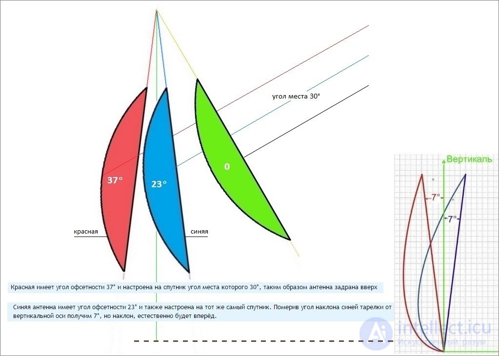
The offset angle is the angle between the normal to the plane of the aperture of the reflector and the axis of the radiation pattern, in other words, the angle between the geometric and electrical axes of the antenna. With axis-symmetric antennas, it is naturally zero. Do offset antennas, as a rule, is 20-28 degrees. The magnitude of the offset angle does not affect the quality of the antenna, but this angle is very useful to know when setting up. In order to orient the offset antenna in a vertical plane, it is necessary to install the reflector at an angle equal to the difference in the satellite elevation angle and offset angle. Offset angle is not always indicated in the specification, but for the vast majority of offset antennas it is easily found by the formula:
f = arccos (B / A)
where f - offset angle ;
B and A are the dimensions of the working part of the reflector in the smaller and larger axes, respectively.
For example, for an antenna with a reflector size of 900x1000 mm, the offset angle is equal to ф = arrcos 0.9 = 25.8 °
From the mechanical characteristics of the antenna should pay attention to the range of azimuth and elevation angles.
The azimuth range for fixed antennas is usually indicated 0-360 °. This means that the antenna can be rotated on a pipe-support in any direction, but in fact it is not always possible. For example, in the specifications of popular domestic antennas of the mark SUPRAL (OAO AlMet, Ulyanovsk) with a diameter of 0.6-1.2 meters, the specification also indicates the range of azimuths 0-360 °, in fact, these antennas are mounted in most cases on the wall bracket, and the angle of rotation is limited by the design of the bracket as well as the offset angle . For antennas with a polar suspension, the azimuth range is also indicated, which is generally not true. The fact is that manufacturers indicate the angle at which the antenna can rotate on the suspension without an actuator. The angle of rotation of the antenna in the real system is somewhat less due to the peculiarities of the operation of the actuator. However, the visible part of the geostationary orbit always fits in the azimuth sector less than 180 °, and the satellites that interest the user are located in an even smaller sector. Therefore, as a rule, the rotation angle of the polar suspension, as well as the offset angle, is enough or almost enough to receive all the necessary satellites.
Angle range. Our country is located quite far from the equator, so even at the southernmost point of the CIS, the highest satellite has an elevation angle of no more than 50 degrees. So, at the maximum elevation angle of the antenna you can ignore, it is certainly sufficient to receive any satellites. But what really matters is the minimum elevation . With axis-symmetric antennas, it is almost always zero, while with offset antennas it can be limited to a value of 8-10, or even 12 degrees. Therefore, if it is necessary to receive satellites that are sufficiently low, it is better to choose an antenna, the design of which allows it to be lowered at low angles.
Work and non-destructive wind. The working wind is the wind in which the antenna continues to operate, while maintaining its electrical characteristics. A non-destructive wind is a wind in which the operation of the antenna while preserving its characteristics is impossible, but after the termination of the effect of the wind, the antenna remains intact and continues to work as before. If the antenna is exposed to wind with greater speed, the antenna requires repair or replacement. If you live in a region with a windy climate, you should choose an antenna for which the speed of the working and non-destructive winds are maximum.

Comments
To leave a comment
The television. Theory. Satellite
Terms: The television. Theory. Satellite