Lecture
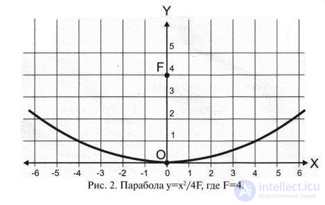
Practically all antennas that are used in individual installations are parabolic mirror antennas made according to a single-mirror design. A mirror antenna is a system of one or more metal mirrors. With other characteristics being the same, the mirror aerials turned out to be the cheapest and most technologically advanced. The surface of the mirror is a clipping of a paraboloid of rotation - a body formed by rotating the curve y = x2 / 4F (parabolas) around the axis OY. Such a mirror concentrates at the point (0; F) the energy of radio waves, if they come from a direction that coincides with the direction of the OY axis.
A fixed antenna is guided to one satellite and is rigidly fixed, it remains stationary during operation. In the general case, signals of a single satellite are received at such an antenna, although, under certain conditions, it is possible to receive signals from one or two neighboring satellites. The mobile antenna (polar suspension) is equipped with an engine, and it can be rotated by aiming at different satellites. 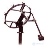 On the one hand, such an antenna has great potential. On the other hand, in a receiving installation with a mobile antenna, besides a mechanical assembly - a polar suspension - a special motor (actuator) and a device that provides automatic antenna pointing (positioner) is required. The system is more expensive, more complex to set up and, unfortunately, less reliable due to the presence of electromechanical components.
In fact, the division of antennas into "polar" and "fixed" is very conditional. For antennas from 60 cm to 1.2 m, so-called “motor suspension” are made - devices combining a polar suspension and a motor with a gearbox (for example, Jaeger SMR-90U), and sometimes also a positioner (Sat-Control SM3D12). With their help, a fixed antenna can be easily turned into a mobile one. The antenna is removed from the standard bracket, a “motorized suspension” is installed in its place, and the same antenna is placed on the “suspension” shaft - now it is “polar”. 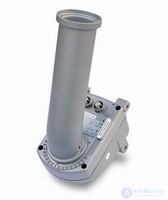 Larger antennas, as a rule, are available in two versions - with a fixed or polar suspension. These are, for example, domestic Supral antennas with a diameter of 1.65 m 1.8 m, 2.0 m and 2.4 m. If you purchased such an antenna in a fixed version, altering it into a polar one may be a problem, you will need not to add but replace some of the suspension parts. On the other hand, the antenna in the polar version can always be used as a fixed one. Instead of an actuator (electric drive with a telescopic rod-pusher), a self-made bar is installed — a section of a pipe or a corner with two holes at the ends. After that, the antenna is tuned to one satellite as fixed. When the owner has the money and desire, instead of the rod, he can put the actuator, connect it through the positioner to the receiver and set up the antenna, like a polar one, to receive multiple satellites.
Setting up a fixed antenna implies a rotation in two planes, in azimuth and elevation, so some sellers and users call fixed antennas “antennas with an azimuth-elevation suspension” or simply “azimuths”, unlike antennas with a polar suspension (“polarok”). There may be confusion. There is a third type of suspension for mobile antennas - the "azimuth-elevation" type of suspension. Antennas with such suspensions are equipped with two engines, one turns the antenna in a horizontal plane (in azimuth), the other in a vertical plane (in elevation). Such antennas are even more difficult to control and expensive, so they are not used in individual receiving systems. They can be found in professional systems for receiving signals from satellites in oblique orbits. These are old satellites that have developed their resource and can no longer be accurately kept in geostationary orbit. Such a satellite begins to write out a “eight” in the sky, the size of which increases with time. In order to qualitatively receive the signal of the “dangling” satellite, it is necessary to adjust the antenna around the clock, following its movements. To control the antenna with the “azimuth-elevation angle” suspension, not a positioner is used, but a more complex device — a tracking system.
Mirrored parabolic antennas are direct focus (Prime Focus) and offset (Offset). Antenna antennas are also called axisymmetric. The mirror of the direct-focus antenna is a paraboloid of rotation, the antenna is round, its geometric axis coincides with the electric axis. The converter is placed on the same axis, which, as a rule, is attached to the edges of the reflector with the help of three or four racks. Offset antenna is a clipping of a paraboloid. As a rule, the notch is formed by the intersection of a paraboloid and a cylinder, the axes of which are parallel. Thus, the mirror of the offset antenna has the shape of an ellipse, and the direction of the electric axis of the antenna differs from the direction of the geometric axis of the mirror at a certain angle. As a rule, the electric axis is 20 ... 30 degrees higher than the geometric axis.
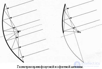 And those and other antennas have their advantages and disadvantages. At the direct-focus antenna, the mirror area is more efficiently used. Offset antenna has the same effective area as a direct-focus antenna with a diameter equal to the size of the offset antenna on a smaller axis. In other words, in order to obtain the effective area of the offset antenna, it is necessary to multiply its physical area by the cosine of the angle between the electrical and geometric axes. In typical antennas, the physical area is used at 86-90%. On the other hand, in a direct focus antenna, part of the surface is obscured by the converter and its fastening elements, while in the offset antenna it is not. Therefore, antennas of small diameter, up to 1.5 meters, in which the converter can obscure part of the area of more than 10%, are usually made offset, and antennas of larger sizes are more often direct focus.
A focal antenna is always raised at some positive angle, therefore it is a “bowl” in which precipitations can accumulate - rain, snow, ice. Offset antennas in our northern latitudes are installed almost vertically, or even generally “look down” - therefore they are deprived of such a disadvantage. On the other hand, on the direct focus antenna downwards the “overwhelms” converter, so you can safely use the irradiator with an unsealed cover or without a cover at all, water and snow will not fall inside. At the offset antenna the converter “looks” upwards, therefore it must be airtight, otherwise the water will get inside and may damage the converter electronics. In addition to water and wind, the converter, and other components of the satellite system, can spoil frequent interruptions of electricity. This question is easily solved; it is enough to buy a gas generator for uninterrupted power supply of receiving equipment.
There is another feature of the use of offset antennas of large diameter in the northern latitudes - they can not always be lowered to a sufficiently small angle. For example, if the satellite’s elevation angle is 5 degrees, the antenna mirror should be directed 15-25 degrees below the horizon. Large-diameter offset antennas that are mounted on a vertical stand, for example, Supral 1.8 m or 2. 4 m, cannot be lowered at an angle less than 11-12 degrees, the lower edge of the antenna rests on the rack. You can get out of position by flipping the antenna mirror together with the mount of the illuminator by 180 degrees, then the electrical axis will be 25-27 degrees lower than the geometric axis, and the antenna will need to be directed above the satellite. However, this requires a serious revision of fasteners.
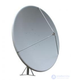 The mirror of small antennas, as a rule, is integral. Large antennas are both solid and modular, consisting of several segments or sectors ("petals"). Prefabricated antennas are easier to transport and assemble. It is considered that one-piece antennas work better than the national ones. This is not quite true, in fact it all depends on the quality of the antenna. For example, the Patriot (USA) team antenna with a diameter of 3.1 m, which is popular in Russia, has a working surface consisting of 8 sectors, and works remarkably well in both the C and Ci ranges. And other common antennas, brand JONSA (Taiwan) with a diameter of 2.4 m, are assembled from 6 segments and work only in the C band, in the C band their gain is about the same as that of the solid antenna of the same 1.8 m diameter.
 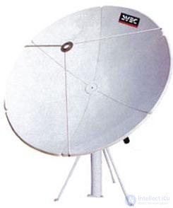 The quality of operation of such prefabricated antennas, as a rule, depends on the quality of the assembly. It is possible to significantly increase the antenna gain, especially in the Ci range, if you remove burrs at the edges of the petals before assembly, and during assembly make sure that no steps are formed at the junction of the petals. Tightening bolted connections is best when the antenna is "face down" on a flat surface or "looks" vertically up into the zenith. In such positions, the mechanical stresses generated by the weight of the antenna are distributed evenly among all connections. If you assemble the antenna in a vertical or inclined position, it is much more likely that it will be “crooked”, skewed.
As a material for the surface of the mirror can be used as a solid metal sheet, and wire mesh. Mesh antennas are lighter in weight and cheaper than solid ones of the same diameter, but they also have a number of drawbacks. In the C band, they work well, but in the C band, their gain is approximately equivalent to the gain of a solid antenna half as large. There is an opinion that the reason for this is the holes in the grid through which the signal allegedly "flows away". In fact, the holes have nothing to do with it. The fact is that the grid is soft and in the intervals between the rigidity elements of the antenna it is stretched, trying to take a flat shape. As a result, the surface of the mesh antenna is not a paraboloid, but a set of flat segments, only approximately close to the paraboloid. One of the laws of radio engineering says that the surface can be considered flat, if the average size of irregularities does not exceed a quarter of the wavelength. In the Ki range, the wavelength is equal to 2.5 cm, therefore the permissible deviation of the surface from the paraboloid is approximately 6 mm. In the C band, the wave is three times longer - 7.5 cm, and the size of the irregularities can reach 19 cm.
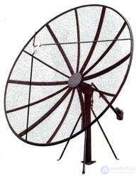 As the advantages of aerial antennas often mention less sail. Indeed, the wind, acting on the mesh antenna, creates a smaller load on the supporting structure than when exposed to a solid antenna of the same size. However, the antenna, as a rule, is attached to the wall or roof - these are rather strong structures capable of withstanding and not such loads. But the strength of the antenna itself at the mesh antennas is much lower. Strong gusts of wind are capable of tearing the net or even completely tearing it out of one or several segments. Such "chipped" mesh antennas are quite often found on the streets of our cities.
The most common materials for satellite dish reflectors are aluminum (more precisely, aluminum alloys) and steel. The electrical properties of the material have virtually no effect on the characteristics of the antenna, so new steel and aluminum antennas work in the same way. Aluminum antennas are lighter, more durable and, as a rule, mechanically stronger, but they are more expensive. In aluminum antennas, the paintwork serves as, so to speak, decorative, and if damaged, only the appearance deteriorates. If the paint exfoliates from the steel antenna, corrosion begins, which may affect not only the appearance, but also the electrical characteristics of the antenna.
One can say the same about plastic antennas, just as the hero of a Soviet film said about brandy: “Armenian is better from cheap, and Georgian vintage is better than French.” Cheap plastic antennas are short-lived: due to temperature fluctuations and simply due to aging, they change shape and warp, which is why they usually work well for one season, especially in a harsh continental climate. Expensive plastic antennas surpass metal in all characteristics: they are not afraid of corrosion, withstand considerable mechanical loads and even shocks without permanent deformation, they are not afraid of temperature drops and uneven heating. Therefore, satellite antennas with a diameter of up to 2.5 m, which are subject to special requirements for quality and reliability, are usually plastic. These are antennas for satellite mobile television journalistic complexes (SNG - Satellite News Gathering), antennas for satellite communications and bidirectional Internet access via satellites. In our country, the most common plastic antenna American-made firms Andrew, Prodelin and Channel Master.
Two -mirror antennas are also mirror antennas, but they consist of two mirrors: the main reflector and the counter reflector. The two-mirror antenna scheme provides a lower level of side lobes of the antenna pattern, so it is often used in transmitting antennas. In the transmitting system, the most expensive parameter is the power of the microwave transmitter, and it should not be allowed to radiate in unnecessary directions. In addition, with a two-mirror antenna, the feed is on the side of the main reflector, which allows the use of a shorter transmission line, and therefore, reduces losses in it. In receiving systems, two - mirror antennas are rarely used, because they are more complex and expensive, and their efficiency is not much higher.
Among the main advantages of the antenna - it is impossible not to notice the huge coverage area, with the possibility of receiving more than 10 satellites at the same time. Easy to install. As well as the reliability of the design also give her the privileges among competitors. As for the minuses that users encountered - this is a fairly high price, as well as a large number of attachments.
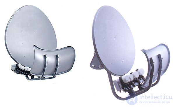
Spherical antennas are special antennas for receiving multiple satellites. With such an antenna, the surface of the mirror is not a paraboloid, but a sphere. For each direction, a spherical antenna has its own focal point, respectively, a separate converter must be installed for each satellite. Unlike a conventional parabolic antenna with several converters, the gain of a spherical antenna for any direction will be almost the same. The efficiency of a spherical antenna is less than a parabolic antenna , so its dimensions must be larger than the dimensions of a conventional antenna, necessary to receive the weakest satellite. In addition, spherical antennas are very difficult to configure, and to work with them require irradiators of a special design, therefore, such antennas are practically not used, at least in our country.
The task of multi-satellite reception without mechanical rotation of the mirror can be solved using spherical or spheroparabolic 3 mirrors. In such designs, the feed is located on an arc of radius r, the center of which coincides with the center of the circle R (Fig. 3).
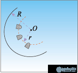
Fig. 3 Spherical antenna

Fig. 3 Spherical antenna
The arc is called the focal line. If you choose r »0.56R, then the wave reflected from the mirror will be close to flat. Such antennas are used in systems of automatic tracking of an object. They use irradiators moving along the focal line, which makes it possible to scan angles in a wide sector. A similar design can be used for multi-site satellite reception. Only instead of one mobile converter on the focal plane, there are several fixed ones oriented to different satellite positions4.
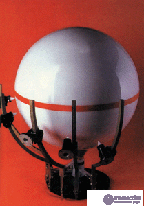
Spherical satellite antenna company "Konkur"
Spherical mirrors are inferior to parabolic in accuracy of focusing and a number of other electrical parameters. However, in some cases, they might be a convenient replacement for the whole fleet of fixed parabolic antennas.
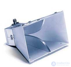 The horn antenna is a horn (socket) to which the waveguide is attached. The main disadvantage of horn antennas is their large size. For a mouthpiece to work, it must converge at a slight angle. Therefore, the length of the horn is obtained much more linear dimensions of its cross section. If we wanted to build a horn antenna equivalent to an antenna with a diameter of 1 m, it would turn out to be 2-3 m long, which, of course, is very inconvenient. Horn antennas are used in radio relay equipment. For receiving from satellites, horn antennas "in pure form" are not used. They are used as feeds for other types of antennas, in particular, mirror ones.
Линзовая антенна представляет собой линзу или систему линз из диэлектрика. Каждый из нас в детстве выжигал на дереве с помощью увеличительного стекла. Линза из диэлектрика так же собирает в одной точке всю энергию радиоволн, приходящих на ее поверхность с определенного направления. Линзовые антенны сложны в изготовлении и дороги, поэтому они в спутниковом телевидении не применяются. Исключение составляет весьма интересный частный случай — сферическая линзовая антенна. При определенных параметрах диэлектрика можно использовать линзу сферической формы. Такая антенна изотропна — она имеет одинаковое усиление при приеме с любого направления, но для каждого направления у линзовый антенны своя точка фокуса. Один сплошной шар из диэлектрика можно использовать как антенну для приема множества спутников, на каждый спутник нужно просто поставить свой отдельный конвертер (головку). Линзовые антенны очень дороги и громоздки, и встретить их можно редко. Тем не менее, они используются, и даже производятся в нашей стране.
Фазированная антенная решетка (ФАР) состоит из нескольких элементарных антенн, сигналы которых суммируются. Как правило, элементарные антенны располагаются в одной плоскости. Фазированные антенные решетки интересны тем, что ими можно управлять: по-разному задерживая по времени сигналы от тех или иных элементарных антенн можно перемещать в пространстве электрическую ось антенны (ось диаграммы направленности), оставляя саму антенну механически неподвижной. В 90-х годах небольшие спутниковые антенны на основе фазированной антенной решетки выпускала фирма Nokia, несколько образцов таких антенн для приема в диапазоне Ки были созданы и в Российских НИИ. Все это плоские (планарные) антенны на основе неуправляемых фазированных антенных решеток . Такую антенну необходимо механически ориентировать по направлению на спутник, как любую другую. Фазированные антенные решетки оказались слишком дороги, поэтому сегодня в спутниковом телевидении они применяются мало. Редкий пример управляемой фазированной антенной решетки для спутникового телевидения — автомобильная спутниковая система А5 американской фирмы KVH. Это плоская антенна высотой всего около 14 см, которая устанавливается горизонтально на крыше автомобиля, на место верхнего багажника или запасной шины Шимкент, и обеспечивает непрерывный прием спутникового сигнала в движении. К сожалению, система работоспособна только в низких широтах (спутник должен иметь угол места не менее 31 градуса) и только в том случае, если спутник не заслоняют какие-либо препятствия, например, лес. В нашей северной лесной стране смотреть спутниковое телевидение в автомобиле пока проблематично.
Американская компания KVH, более 25 лет занимающаяся разработкой технологий в области коммуникаций, навигационного оборудования и систем дистанционного управления вооружением, разработала антенну TracVision, которая полностью изменила представление о спутниковом телевидении. Компания доказала, что принимать спутниковые программы вы можете и в автомобиле, даже на скорости выше 200 Км/ч, хотя производитель гарантирует устойчивость антенны при скорости ветра до 165 Км/ч. Правда, для этого пришлось создать новую антенну, обладающую двумя признаками, не свойственными обычным параболическим аналогам:
Минимальным сопротивлением воздушному потоку (читай хорошей аэродинамикой)
Высокой скоростью подстройки под спутник

В том, что вы видите на фотографии, трудно угадать спутниковую антенну. Но вы убедитесь в том, что это антенна, когда включите автомобильный телевизор. Нет, она не разложится, как крышка лунохода и не начнёт вращаться вокруг своей оси - она итак находится в рабочем состоянии, а вся конструкция скрыта внутри чрезвычайно низкого корпуса.
Принцип действия антенн TracVision A7 - плоская фазированная антенная решётка с электромеханическим приводом. Проще говоря, если в обычной спутниковой тарелке есть только один приёмник, то в TracVision A7 на одной плоской поверхности установлены две сотни маленьких приёмников на одной поверхности. За подобной конструкции достигается эффект усиления, сопоставимый с оффсетной параболической антенной диаметром 60 см.
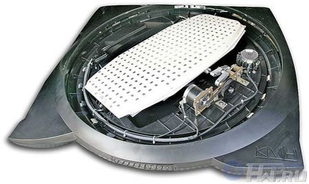
Электрический привод способен вращать решётку на 180 градусов вокруг своей оси, а так же изменять её угол наклона к горизонту настолько быстро, что антенна реагирует даже на резкие манёвры водителя.
Физические характеристики:
Высота/диаметр антенны: 19.5х77.5 см
Вес антенны: 13.6 кг
Размеры приемника: 29.7х29х7.6 см
Вес приемника: 2 кг
Потребляемая мощность: 30 Вт
Напряжение питания: 12 В пост. тока (автомобильный аккумулятор) (9 – 16 В)
Характеристики окружающей среды
Диапазон рабочих температур: От –25оС до +55оС
Диапазон температур хранения: От –29оС до +60оС
Скорость поворота/слежения: 30 градусов в секунду
Сила ветра (ЕМЕ): 100 миль в час
Стабилизация: 2-осевая активная гироскопическая стабилизация
Скорость поворота антенной решётки составляет 30 градусов в секунду, можете сами рассчитать, как резко надо входить в поворот, чтобы она сбилась.
Вся конструкция собрана в один блок весом 23 Кг, что сопоставимо с пустым аэродинамическим багажником Thule. Вся электроника и механика находятся под надёжной защитой крепкого пластикового кошуха. Ни колебания температур, ни дождь, ни град не страшны этой антенне. Установщики уверяют, что пластиковый кожух даже выдержал удар о балку гаража, когда новоиспечённый владелец TracVision по привычке решил въехать на подземную парковку, забыв о тарелке.
Зональная антенна или антенна Френеля , представляет собой поверхность, на которой отражающими радио-волны делаются только некоторые выделенные зоны. Форма и размеры этих зон выбираются так, чтобы отраженные волны складывались в одной точке. Наиболее известна зональная антенна Френеля . Она состоит из набора плоских концентрических колец, расположенных в одной плоскости. Антенна Френеля проста в изготовлении и недорога, но ее эффективность почти вдвое ниже, чем у зеркальной или линзовой антенны, поскольку используется не вся площадь, а только ее отражающая часть. В журнале «Теле-Спутник» №6-98 описана методика расчета и изготовления антенны Френеля .
Comments
To leave a comment
The television. Theory. Satellite
Terms: The television. Theory. Satellite