
Lecture
Piezoelectric emitter, piezo emitter — an electroacoustic device capable of reproducing sound or emitting ultrasound by virtue of the inverse piezoelectric effect.
ZP piezoelectric sound emitters go by a number of other names: piezo buzzer, piezo emitter, piezoceramic emitter, piezoceramic bells, piezoceramic bells with an acoustic chamber, piezoceramic sounder, audible signaling device, piezo siren.
The ZP piezo emitters presented here are characterized by their sound pressure (75 dB, 90 dB), resonance frequency (1000 Hz – 5000 Hz) and operating voltage (3 V – 9 V). These are the parameters to pay attention to first when choosing a piezo emitter. The maximum elevated operating ambient temperature is +60°C, and the minimum low operating temperature is -30°C.
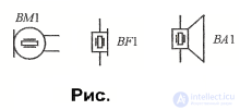
The letter code for piezoelectric elements and resonators is the Latin letters BQ.
Piezoelectric transducers are widely used in audio engineering: in phonograph pickups, microphones and loudspeaker drivers. The operating principle of these devices is indicated by the piezoelectric effect symbol, which differs from the basic conventional graphic symbol only in its smaller size and the absence of leads from the plates (see fig. , BM1, BF1, BA1).
Their operating principle is based on the piezoelectric effect, discovered by the brothers Pierre and Jacques Curie as early as 1880. It consists in the fact that in certain crystals (quartz, tourmaline, Rochelle salt, etc.) electric charges appear on their faces under the action of applied mechanical forces. Depending on the type of crystal, charges can also appear under shear, bending and torsion. In addition to the "direct" effect described above, there is also an inverse effect (theoretically predicted in 1881 by Lippmann and experimentally confirmed in the work of the Curies). If an electric voltage is applied to the plates of a piezoelectric crystal, the crystal begins to deform: it lengthens, bends, twists, and so on. The idea of using such crystals in the design of electroacoustic transducers appeared very long ago and was implemented in the period 1920–1940 in phonograph pickups, microphones, accelerometers, ultrasonic transducers, etc.
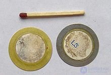
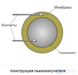
A piezoelectric emitter consists of a metal plate on which a layer of piezoelectric material is deposited, with a conductive coating on its outer side. The plate and the coating serve as the two contacts. To increase the loudness, a small horn in the form of a metal or plastic dome with an opening may be attached to the metal plate[1]. A recess in the housing of the device in which the piezo emitter is used can also serve as a horn.
Piezoelectric emitting elements may have a spherical or cylindrical surface shape[2].
In general, piezoceramics is an ungrateful substance when it comes to transferring its vibrations to the air. Let us illustrate this with an example. Suppose a standing wave is excited in a piezoceramic sample. It is characterized by a certain value of sound pressure and by the amplitude of particle displacement during the vibrations. Let us pose a question. How do the vibration amplitudes of particles in the ceramic and in the air differ when the sound pressures in both are equal? Answer: by a factor of 75 thousand. The reason is that the product of the density of air and the speed of sound in air is 75 thousand times smaller than the corresponding product for ceramics. The share of radiated power is even smaller — one seventy-five-thousandth squared! Transmitting sound into water is a different matter. Its density is a thousand times greater and the speed of sound is five times greater than in air. That is why hydroacoustic engineering and airborne acoustic engineering have little in common. Despite this pessimistic premise, considerable loudness can be achieved with piezoceramics. Individual piezoceramic transducers can develop a sound pressure of up to 130 dB at a distance of 1 m. How can one get a feel for this figure? It is the pain threshold. The absolute value of the sound pressure corresponding to 130 dB is 60 N/m2, or 6 kgf/m2. Such a sound presses on the eardrum with a force of roughly 0.2 g. Who doesn't know what a bimetallic plate is? Two sintered metal plates with different coefficients of linear expansion bend when heated by an amount many times greater than the thermal elongation. But what if one of the plates lengthened while the other shortened?.. The essential element of an electroacoustic transducer based on piezoceramics is a bimorph structure made of two thin piezoelectric elements, one of which stretches when a voltage is applied while the other contracts. Most often a third element, a metal diaphragm, is glued between the piezoelectric elements. The metal gives the structure strength. Even more often it is enough to use a single piezoelectric element, with the diaphragm itself serving as the second element of the bimorph (see fig. 1). Such structures are called bimorph piezoelectric elements, or piezo units.
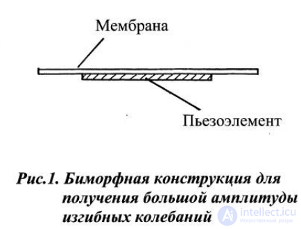
Their usual dimensions are 10 – 60 mm in diameter and 0.2 – 1.5 mm in thickness. The diameter of the piezoelectric element is usually 1.5 – 2 times smaller than the diameter of the diaphragm. When a voltage is applied to the piezoelectric element, its diameter either increases or decreases, depending on the polarity. The diameter changes by about 0.05 µm for every 10 V of voltage. However, owing to bending, the edges of the diaphragm rise or fall by 20 µm. Thus we have converted the small expansion of the piezoelectric element into a bending displacement at the edge of the diaphragm that is 400 times greater. The 75000 mentioned earlier has already turned into 187! But let us go further. Now we need to use the phenomenon of resonance. After all, at resonance the amplitude increases by a factor equal to the quality factor. The usual quality factor of a piezo unit is 50 – 70, and now the notorious 75000 turns into an ordinary three. It would seem the problem is solved, but not so fast! Despite the large amplitude, the piezo unit does not sound. It does not radiate sound. A small piezo unit cannot be heard at all. A larger piezo unit can be heard, but only faintly. What is the reason? Let us turn to fig. 2, which schematically shows two phases of vibration of a round bimorph element. The points a mark the circle of zero amplitude — the nodal circle.
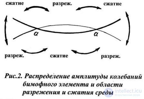
At the edge and at the center of the element the amplitude is maximal, but the vibrational motion is in antiphase. For each phase of vibration, three pairs of rarefaction–compression regions of air are formed. Since the size of the piezo unit is smaller than the sound wavelength (for a frequency of 2 – 3 kHz the wavelength is 110 – 170 mm), the rarefaction and compression regions cannot drive a wave onward, and within half a period they manage to "collapse" pairwise, so that the pressure around the element is constantly equalized. The paths of pressure equalization are shown by double-headed arrows. This phenomenon is called an acoustic short circuit. To make our device sound, the acoustic short circuit must be eliminated. This task is by no means difficult, and quite a few methods have been devised that have proven themselves in practice. The design and external shape of the device depend on which method is used.
Alarm sounders
A piezoceramic alarm sounder (piezo siren, signaling device) is a sound-emitting device designed to attract attention over a relatively large distance or against background noise. It is either a bare electroacoustic transducer or is equipped with a built-in audio-frequency generator powered from a DC voltage source. Compared with bells, alarm sounders must develop a higher sound pressure. This is achieved in two ways at once. First, a higher alternating voltage (tens of volts) is applied to the piezo unit; second, design measures are taken to increase the radiating surface. The simplest way to turn a bell with an acoustic chamber into an alarm sounder is to fit it with a horn. A horn is a tube with an increasing cross-sectional area. The sound source sits at the narrow start of the tube, and the wide end is the emitting one. In piezoceramic alarm sounders, folded horns are used to reduce the overall dimensions. Figure 7 schematically shows a vertical section of an alarm sounder with a folded horn. The sound wave from the opening of the acoustic chamber propagates radially through a labyrinth, changing direction (up and down).
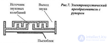
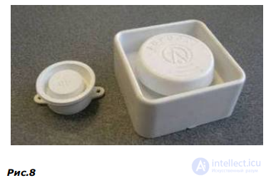
With each change of direction, the cross-section grows larger. As a result, the area of the radiating annular opening is many times greater than the area of the original sound source. An example of horn-type sounders — the OSA-100 and OSA-110 — is shown in the photograph, Fig. 8.
Another way to increase the radiating surface is to use a diffuser cone or a diaphragm, for example as shown in Fig. 10. The base of the funnel-shaped cone is glued to the center of the piezo unit, at the point of maximum vibration amplitude.
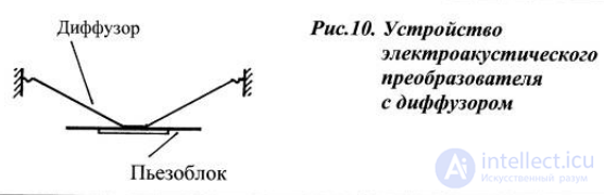
The peripheral part of the piezo unit serves as a counterweight. Thus, the cone acts as the sound-radiating element, while the piezo unit acts as the drive.
Russian-made piezo emitters are designated by the letters "ZP" (zvukoizluchatel piezoelectric, i.e., piezoelectric sound emitter) and a series number. The most common emitters in Russian consumer electronics are the ZP-1 and ZP-3.
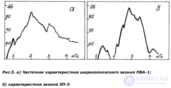
ZP-type sound emitters are driven by applying an alternating voltage of a specific frequency and amplitude, usually 3…10 V. At the frequency where the sound pressure is at its maximum, it can reach 75 dB at a distance of 1 meter from the emitter. The resonant frequency for most piezo emitters is 1…4 kHz. This accounts for their characteristic, recognizable sound resembling a "beep".
What voltage can be applied to an audio piezo transducer? Just as iron can be magnetized and demagnetized by a strong current, piezoceramics can be given piezoelectric activity and deprived of it by high voltage. Therefore, the operating voltage must not exceed 30-40% of the process voltage used to impart piezoelectric properties to the ceramic. Approximately 350 V per 1 mm of piezoelement thickness is permissible. The thickness of the piezoelement in a sounder is usually 0.2 - 0.3 mm. Hence, the maximum voltage will be 70 – 100 V.
What is the impedance of an audio piezo transducer? If the frequency of the current is away from the transducer's resonant frequency, its impedance is determined by the static capacitance. This capacitance usually lies in the range of 20 to 50 nanofarads. If the piezo unit of the transducer uses two piezoelements on opposite sides of the membrane, this range doubles. At the resonant frequency, the impedance decreases by a factor equal to the quality factor, but still remains fairly significant. In practice, the impedance at resonance usually lies in the range of 0.5 to 2.0 kΩ. A particularly powerful transducer, the one shown in Fig. 13, has an impedance at resonance of about 100 Ω.
What resonant frequency are sounders designed for? The actual frequency of most piezoceramic sounders lies in the range of 2.5 to 3.5 kHz. This range corresponds to the maximum sensitivity of the human auditory system and, "fortunately," is the most natural for piezoceramic sound transducers.
Note a general feature of piezoceramic sound sources: the ranges of possible values of the parameters mentioned are small. This is not comparable to capacitors and resistors, where the ranges of capacitance and resistance are practically unlimited. The question naturally arises: what if...? If the dimensions of the membrane and the piezoelement were increased several times, could the consumed and radiated power be increased substantially? It turns out that it cannot. The obstacle is the scale factor. If an ant can lift a matchstick, that does not mean that, with the weight of a human, it could lift a reinforced concrete slab. A grasshopper with our weight would not jump two hundred meters. A grasshopper, a human and an elephant are made of the same biological material, and a change in body size does not lead to a proportional change in capabilities. We can proportionally increase the dimensions of the piezo unit, but we cannot correspondingly change, to any noticeable extent, the parameters of the material it is made of.
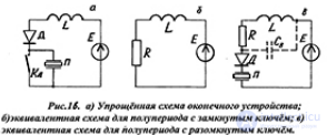
We have established that to obtain sufficient sound volume, an alternating voltage of tens of volts must be applied to the sounder. But what if a lower-voltage power supply is used, such as 6, 9 or 12 volts? Perhaps the simplest way to raise the voltage across the sounder is to use the self-induction EMF of an inductor. The output stage circuit with a choke is simple, but its operating principle needs explanation, since this will help in choosing the circuit component parameters correctly. Let us turn to the figure. Fig. 16a shows a simplified circuit of the output stage, including an EMF source E, a choke L, a diode D, a piezo transducer P and a switch S. The switching frequency is set equal to the resonant frequency of the transducer. For half of the transducer's oscillation period the switch is closed and, during this time, energy accumulates in the coil. During the second half of the period the switch is open and the self-induction EMF acts on the transducer.
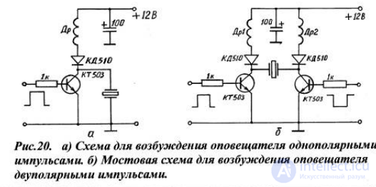
Now let us present two practical circuits designed to "drive" the OSA-110-B sounder described above. Fig. 20a shows a circuit for powering the sounder with unipolar pulses. The circuits use chokes with parameters close to the calculated ones: L = 15 mH, R = 18 Ω. These parameters were calculated based on the "desired" sound pressure of 107 dB. Fig. 20b shows a bridge circuit for powering with bipolar pulses ("kicks" in each half-period, but with a change of sign). The latter circuit gives an additional volume increase of 5-6 dB.
Piezo emitters are widely used in various electronic devices — alarm clocks, telephones, electronic toys and household appliances. They are often used as emitters of ultrasonic vibrations in rodent and insect repellent devices, air humidifiers, ultrasonic "washing machines" (see ultrasonic cleaning), piezo lighters, piezoelectric transformers and various alarm sensors.
A piezo emitter can also be used as a piezoelectric microphone or sensor.

Comments