
Lecture
Acoustic (more precisely, electroacoustic) devices are devices that convert the energy of electrical oscillations into the energy of sound or mechanical vibrations, and vice versa. The graphic symbols of these devices are built on the basis of the general symbols set by the standard for each type [8]; the basic letter code is the letter B (the exception is sound signaling devices).
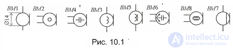
To designate a microphone (code BM), a symbol is used that schematically depicts the design of one of the first carbon microphones (in it, sound was converted into electrical oscillations by the change in contact between a carbon ball and a diaphragm). The side-view drawing of these two parts of the microphone became its first symbol. Today this symbol (Fig. 10.1, BM1) is used as the basic graphic symbol of a microphone. The lead lines are directed either in opposite directions (BM1) or in the same direction (BM2).
The operating principle and other features of microphones are indicated by special marks. Thus, the carbon microphone mentioned above is marked on diagrams by a small circle in the middle of the symbol (Fig. 10.1, BM2), an electrodynamic one by a coil symbol made of two semicircles (BM3), an electromagnetic one by the same mark supplemented with a magnetic core symbol (BM5), and an electrostatic (condenser) one by a capacitor symbol (BM4). To show a stereophonic microphone on a diagram, a stereophonic device mark is introduced into the symbol: two mutually perpendicular arrows (BM6). Such microphones are shown with the required number of leads, enlarging the symbol if necessary.
The general symbol of this group of acoustic devices also underlies the graphic symbols of laryngophones, special microphones pressed against the neck near the larynx and intended for telephone communication in noisy environments (aircraft, tanks, etc.). The distinguishing feature of a laryngophone is a chord parallel to the diaphragm symbol (BM7). The method of converting sound into electrical oscillations in the laryngophone symbol is indicated by the same marks as for ordinary microphones. As an example, Fig. 10.1 (BM8) shows the symbol of a piezoelectric laryngophone (the piezoelectric transducer symbol is a narrow light rectangle with two short strokes denoting the electrodes of the piezoelectric element).
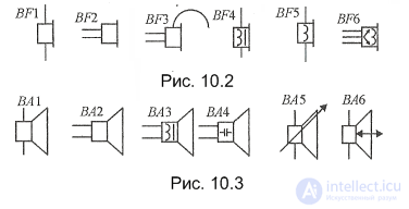
The graphic symbols of acoustic devices that convert electrical oscillations into sound, namely telephones (earphones) and loudspeaker drivers, are built on basic symbols that schematically reproduce their side view (see Fig. 10.2 and 10.3, respectively).
The code for telephones is BF, and for loudspeaker drivers it is BA. As with microphones, the leads of these acoustic devices may be directed either in the same direction or in opposite directions (see Fig. 10.2, BF1, BF2; Fig. 10.3, BA1, BA2). To indicate the operating principle and other features, the same marks are used (the symbol size in this case is increased approximately twofold). To emphasize that a telephone is fitted with a headband, a small arc is added to the basic symbol (see Fig. 10.2, BF3). A stereophonic telephone is shown with the required number of leads (BF6).
Next to the reference designation of a dynamic driver, its type is usually indicated
The general loudspeaker driver symbol is used to designate subscriber loudspeakers, as well as entire acoustic systems containing several drivers. The possibility of adjusting the sound volume (for example, in a subscriber loudspeaker) is shown by an arrow crossing the symbol at an angle of 45° (see Fig. 10.3, BA5). A driver that alternately serves as a loudspeaker and a microphone (it is often used this way in compact simplex communication equipment) is shown on diagrams with a conversion reversibility mark, a double-headed arrow on the axis of symmetry (see Fig. 10.3, B1).
The graphic symbols of heads used in sound recording are based on a general symbol. The recording method (mechanical, magnetic, optical) and the purpose of the head (recording, playback, erasing) are denoted in the symbols of this group of devices by special marks.
Thus, heads for magnetic recording (code BS) use the same symbol with the magnetic device symbol, an open ring (Fig. 10.4, B1). The purpose of the head is shown by an arrow: if it is used for playback, the arrow points toward the leads (see Fig. 10.4, BS1, BS4; Fig. 10.5, BS1— BS4), and if for recording, toward the narrowed part of the symbol (Fig. 10.4, B2). A universal head used for both recording and playback is denoted by a double-headed arrow (Fig. 10.4, B2), and a head intended for erasing by a cross mark inside the symbol (see Fig. 10.4, B3).

The same approach is applied to the symbol of a stereophonic magnetic head, but considering that it essentially consists of two independent heads, it is often shown as two identical symbols enclosed in a contour of dashed lines (shield) or dash-dot lines. The number of recorded or played tracks is shown by the corresponding digit with a leader line touching the magnetic device mark (see Fig. 10.4, B4).
The purpose of optical heads (designation B) is judged by the parallel arrows placed near the narrowed part of the symbol. If they point toward it, the head is a playback head (see Fig. 10.4, B5), and if away from it, a recording head (B6).
Heads for mechanical sound recording and playback (letter code BS) are shown by the standard symbol, but with a short stroke symbolizing the stylus of a pickup or recorder (Fig. 10.5)
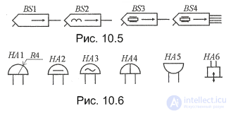
The operating principle of a mechanical head (pickup, recorder) is shown by the same marks as in the symbols considered above. As an example, Fig. 10.5 shows the symbols of an electrodynamic (BS2) and a piezoelectric (BS3) pickup head. If necessary (for example, if the head is stereophonic and has more than two leads), the symbol size may be enlarged to the required dimensions.
Acoustic devices also include all kinds of electric bells, gongs, sirens, horns, and buzzers, which are sound signaling devices (letter code HA), as well as ultrasonic hydrophones (heads of devices for underwater operation).
The general symbol of an electric bell is a stylized side-view drawing of its sounding element, a bell, with the designation HA1 (Fig. 10.6). A direct-current bell is marked on diagrams with the direct-current symbol, a straight line segment (see Fig. 10.6, HA2), and an alternating-current one with a sine wave segment (HA3). An electric single-stroke bell (gong) is shown by the basic symbol crossed by a line parallel to the leads (HA4).
Low-power sound sources, buzzers (used, for example, to call subscribers in field telephones), are denoted by a semicircle with lead lines from the round part (HA5).
The graphic symbol of an ultrasonic hydrophone is based on a somewhat enlarged (relative to that shown in Fig. 10.2) telephone symbol. The ability to emit and receive ultrasonic oscillations is indicated by a double-headed arrow crossing the side of the symbol opposite the leads.

Comments