
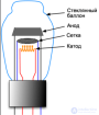
The triode is the first amplifying valve: a control grid is added between cathode and anode. It sits close to the cathode, so its voltage controls the current μ times more strongly than the anode does: the current follows the combination Ug1 + Ua/μ. Here μ = 35.
The circuit is the classic common-cathode stage. The cathode resistor (1.5 k) generates its own negative grid bias: the valve current lifts the cathode about 1.8 V above ground while the grid sits at ground through the generator. The 100 k anode resistor turns the current swing into a voltage swing. No separate bias supply is needed.
This page is a utility for simulating triode: voltage amplifier online with specified initial values.
Using the model. Wait for the cathode to warm up (the T readout beside the valve); the operating point then settles at Ia ≈ 1.2 mA with about 130 V on the anode — roughly half the supply, as linear operation requires.
The scopes show the input on the grid and the output on the anode. The output is 18 times larger and inverted: a more positive grid means more current, which means a lower anode voltage. Use the input-amplitude slider to push the signal to 3–4 V and watch the peaks clip as the valve runs into cut-off and into grid current. The gain is always below μ = 35: part of the swing is lost across the valve's own internal resistance, and the larger the anode resistor, the closer you get to μ.



Comments