
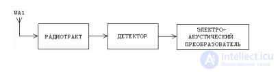
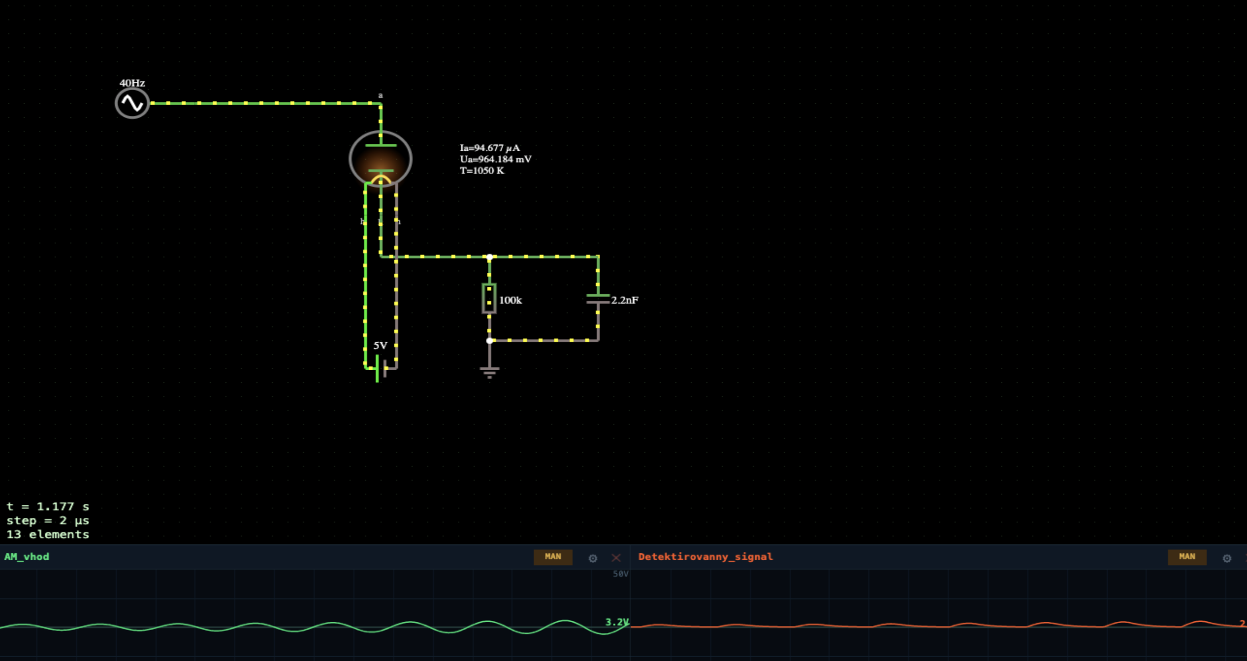
A complete AM receiving chain built around a single vacuum diode — in effect a valve crystal set.
The antenna picks up the band: in this model three stations at once — carriers at 3000, 2710 and 2433 Hz, modulated with 12, 13 and 14 Hz tones. Through a 1 nF coupling capacitor the signal reaches the input tuned circuit, 100 mH ∥ C: at resonance its impedance is high, so it picks out one station and suppresses the neighbours. The kenotron then removes the negative half-cycles, and the 100 k ∥ 33 nF load smooths the carrier while still following the modulation — what is left is the envelope, i.e. the audio. It goes to the headphones (audio output).
The envelope-detection condition is 1/fcarrier « RC « 1/fmodulation. Here RC = 3.3 ms, which is 10 carrier periods and 0.04 modulation periods — right in the middle. Make RC much longer than the modulation period and the same diode with the same RC network becomes an ordinary rectifier.
This page is a utility for simulating crystal-set am receiver on a kenotron: envelope detector online with specified initial values.
Using the model. Wait for the cathode to warm up, then turn the tuning slider — it is the input tank capacitance. Three settings correspond to the three stations:
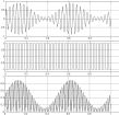
Compare the two upper scopes. The Antenna trace is a mess: three carriers overlapping and beating against each other. The Kontur trace is one clean carrier — the tuned circuit has done its job. The lower Zvuk scope shows what the headphones would hear.
Tune between stations and the tank amplitude collapses, the audio gets quieter and dirtier. Raise the load capacitor from 33 nF to 1 µF and the detector can no longer follow the modulation, turning into a rectifier: the audio disappears and only a DC level remains. Drop it to 1 nF and the carrier reappears at the output instead.




Comments