
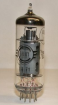
A vacuum diode passes current one way only: the hot cathode emits electrons, the cold anode does not. The valve therefore keeps only the positive half-cycles of an alternating voltage. The current follows the Child–Langmuir three-halves power law, Ia = K·Ua1.5, as long as the cathode emission can supply it.
This is the classic half-wave power-supply rectifier: 250 V, 50 Hz mains → kenotron → 47 µF reservoir capacitor → 10 k load. The capacitor charges on the peaks and discharges into the load between them; the time constant RC = 470 ms is 23 times longer than the mains period, so the output is nearly flat DC.
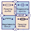
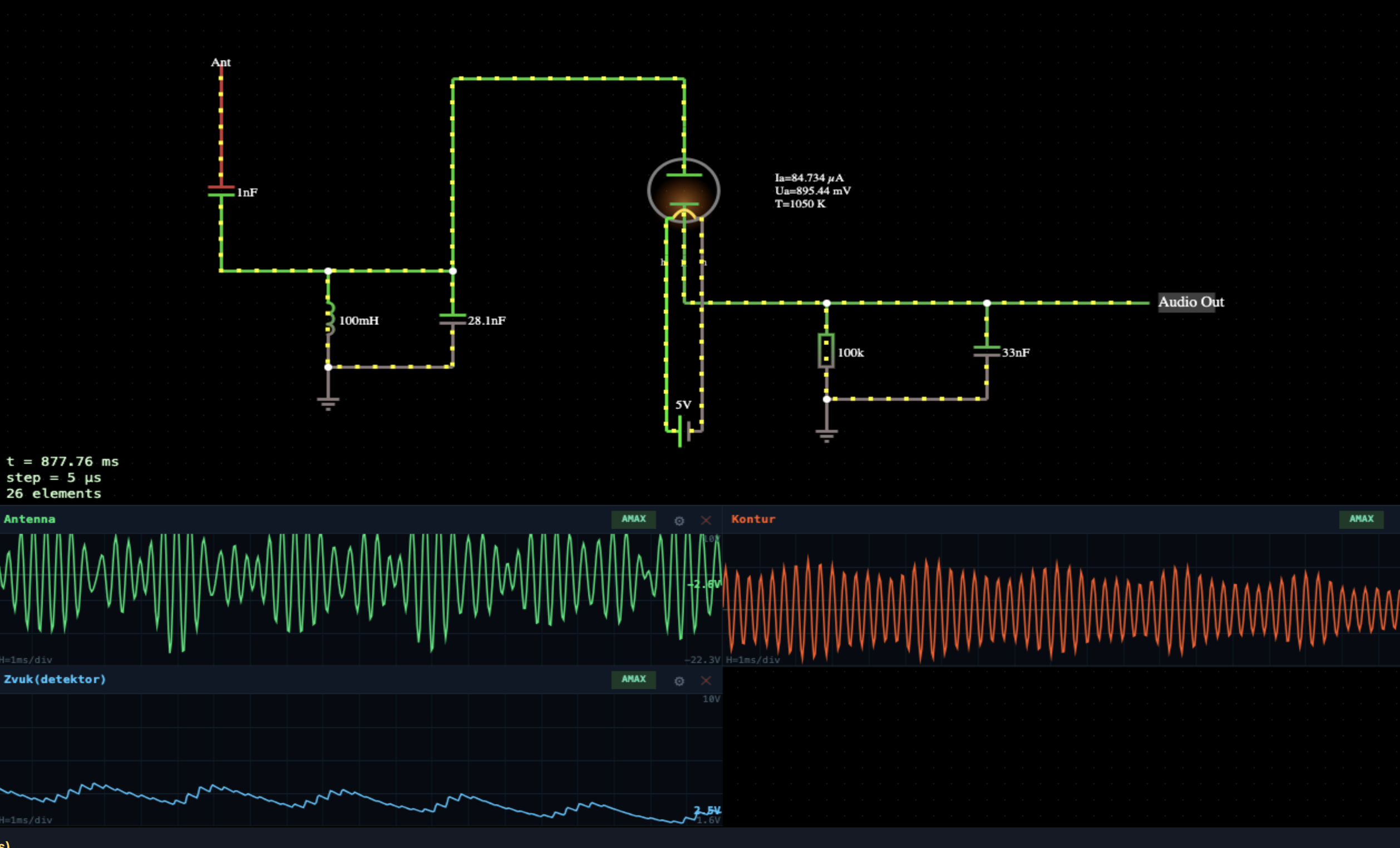
Note that the AM detector is built from the very same three parts. The only difference is the time constant: in a rectifier RC is far longer than the input period, so the envelope is deliberately smoothed away; in a detector it is far shorter than the modulation period, so the envelope survives.
This page is a utility for simulating kenotron: ac rectifier online with specified initial values.
Using the model. At first there is no rectification at all: the cathode is cold. The heater (the two lower pins, 5 V) warms it in about a second — watch the T readout beside the valve. Turn the heater slider down and the emission can no longer supply the load, so the output sags; set it to zero and there is no output at all. That is exactly how a kenotron with a burnt-out filament behaves.
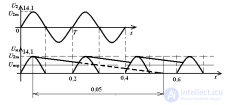
The upper scope shows the AC mains (±250 V), the lower one the rectified output: about 155 V with only 3 % ripple. The output sits below the input peak because part of the voltage is dropped across the valve itself and the capacitor discharges between pulses.
Reduce the capacitor to 1 µF and the ripple grows tenfold into a sawtooth. Reduce the load resistance and the current rises, the capacitor discharges faster and the ripple grows again. That is the central trade-off of every rectifier.



Comments