
Air Propeller: Design, Efficiency and History

Lecture 9 min.


Air Propeller: Design, Efficiency and History
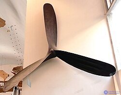
Propeller of the German airship SL1 (1911), 4.4 m in diameter
Air Propeller: Design, Efficiency and History
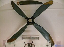
Propeller of the British airship R29 (1918) in a Scottish museum
Air Propeller: Design, Efficiency and History
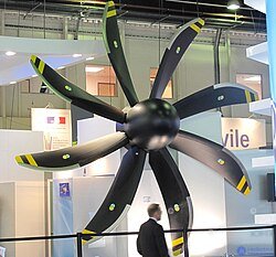
Modern propeller of the A400M transport aircraft
Air Propeller: Design, Efficiency and History
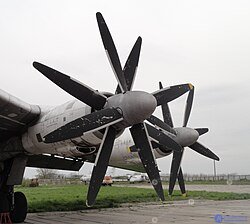
AV-60K propellers of the Tu-142 aircraft

An air propeller (English propeller < Latin propellere — "to drive forward"[1]) is a bladed propulsor that, when rotating, creates thrust by throwing air rearward with some additional velocity[2]; it is driven by an engine and converts the engine torque into thrust.

Air propellers that perform additional or other functions (besides that of a propulsor) have special names: rotor, cruise propeller, main rotor (of rotorcraft), tail rotor, fenestron, impeller, fan, wind turbine, propfan.

The air propeller is used as a propulsor for aircraft (airplanes, autogyros, cyclogyros (cyclocopters) and helicopters with piston and turboprop engines), and in the same capacity for ekranoplans, airsleds, airboats and air-cushion vehicles.
On autogyros and helicopters the air propeller is also used as a main rotor, and on helicopters also as a tail rotor.

An air propeller working as a propulsor, together with the engine, forms a propeller-engine installation, which is part of the powerplant.

Technical parameters

The propeller blades, as they rotate, catch the air and throw it in the direction opposite to the motion. A zone of reduced pressure is created in front of the propeller, and a zone of increased pressure behind it.

  • Depending on the mode of use, air propellers are divided into tractor and pusher types (the former are located ahead of the engine, the latter behind it)
  • Depending on whether the blade pitch can be changed, air propellers are divided into fixed-pitch and variable-pitch propellers

The defining parameters are the diameter and the pitch of the propeller. The propeller pitch corresponds to the imaginary distance the propeller would advance, screwing itself through an incompressible medium in one revolution. There are propellers whose pitch can be changed either on the ground or in flight. The latter came into use in the late 1930s and are used on virtually all aircraft (except some ultralights) and helicopters. In the former case, pitch change is used to produce high thrust over a wide range of speeds at little-changing (or constant) engine rpm corresponding to its maximum power; in the latter, it is used because the rotor speed cannot be changed quickly.

The rotation of the propeller blades produces a turning effect on the aircraft, for the following reasons:

  • Propeller reaction torque. Any air propeller rotating in one direction tends to roll the airplane, or to turn the helicopter, in the opposite direction. This is what causes the asymmetry in the lateral control of an airplane. For example, an airplane with a left-handed (counterclockwise) propeller performs turns, flips and barrel rolls to the right much more easily and quickly than to the left. This same reaction torque is one of the causes of the uncontrolled sideways swing of an airplane at the start of the takeoff run
  • Propeller slipstream swirl. An air propeller swirls the airflow, which also causes asymmetric blowing over the wing surfaces and tail unit on the right and on the left, different wing lift on the right and on the left, and a difference in the airflow over the control surfaces. The asymmetry of the flow is clearly visible in agricultural aviation when observing the movement of the sprayed substance
  • Propeller gyroscopic moment. Any rapidly rotating body has a gyroscopic moment (the spinning-top effect), which consists in a tendency to preserve its position in space. If the axis of rotation of a gyroscope is forcibly tilted in some direction, for example up or down, it will not simply resist this deflection but will move off in the direction perpendicular to the applied action, that is, in this case, to the right or to the left. Thus, when the pitch angle is changed in steady flight, the airplane will tend to change its heading on its own, and when a turn begins, the airplane tends to change its pitch angle on its own
  • Moment caused by asymmetric flow around the propeller. In flight, the propeller axis is inclined to the direction of the oncoming flow by the angle of attack. As a result, the descending blade meets the flow at a larger angle of attack than the ascending blade. The right-hand part of the propeller will produce more thrust than the left-hand part. Thus a yawing moment to the left will be created. This moment is greatest at maximum engine power and maximum angle of attack

All 4 causes of the turning tendency — reaction torque, slipstream action, gyroscopic moment and asymmetric flow around the propeller — always act in the same direction: with a left-handed propeller they turn the airplane to the right, and with a right-handed propeller, to the left. This effect is particularly strong on powerful single-engine airplanes at takeoff, when the airplane moves at a low forward speed and the effectiveness of the aerodynamic controls is low. As speed increases, the turning moment weakens owing to the sharp increase in control effectiveness.

To compensate for the turning moment, all airplanes are made asymmetric; at the very least, the rudder is deflected from the central construction axis of the airplane.

Apart from the gyroscopic effect, coaxial air propellers are free of two of these 3 drawbacks.

Reaction and gyroscopic moments are also inherent in all turbojet engines and are taken into account in aircraft design. To compensate for the reaction torque of a helicopter rotor, one has to use a tail rotor, which prevents rotation of the fuselage, or use several main rotors (usually 2).

Efficiency

The efficiency of an air propeller is the ratio of the useful power spent on overcoming the resistance to the motion of the aircraft to the engine power. The closer the efficiency is to 1, the more effectively the engine power is used, and the higher the speed or payload that can be attained with the same power-to-weight ratio.

Advantages and disadvantages

The efficiency of modern air propellers reaches 82—86%, which makes them very attractive to aircraft designers. Aircraft with turboprop powerplants are considerably more economical than aircraft with jet engines. However, the air propeller also has some limitations, both of a design and of an operational nature. Some of these limitations are described below.
  • "Lock-up effect". This effect arises either when the propeller diameter is increased or when the rotational speed is increased, and manifests itself as the absence of a thrust increase with increasing power delivered to the propeller. The effect is associated with the appearance of regions of transonic and supersonic airflow on the propeller blades (wave drag crisis).
    This phenomenon imposes substantial limitations on the technical characteristics of aircraft with propeller-engine powerplants. In particular, modern propeller-driven aircraft generally cannot reach speeds above 650—700 km/h. The fastest propeller-driven aircraft, the Tu-95 bomber, has a maximum speed of 920 km/h; there the lock-up problem was solved by using 2 coaxial counter-rotating propellers with permissible blade sizes.
  • Increased noise. The noise of modern aircraft is currently regulated by ICAO standards. A classically designed air propeller does not meet these standards. New types of air propellers with scimitar-shaped blades produce less noise, but such blades are very complex and expensive to manufacture.

History

Air Propeller: Design, Efficiency and History
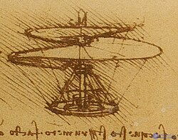
Drawing of Leonardo da Vinci's helicopter, 1480s

The idea of the air propeller derives from the Archimedes screw.

A drawing by Leonardo da Vinci is known showing the prototype of a helicopter with a lifting rotor. The rotor still looks like an Archimedean screw.
Air Propeller: Design, Efficiency and History
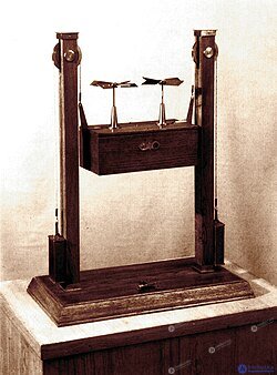
M. V. Lomonosov's aerodromic machine. Model

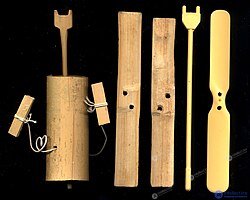
In July 1754, Mikhail Lomonosov demonstrated an aerodromic model. Its blades are already flattened, which brings them closer to their modern form. It is assumed that Lomonosov drew on a Chinese children's toy, the bamboo-copter[Eng.].
Air Propeller: Design, Efficiency and History
The modern Japanese toy taketombo, a bamboo-copter[Eng.] descended from the Chinese version. Left: bamboo; right: plastic

Advanced developments

Aircraft designers resort to certain technical devices so that such an efficient propulsor as the air propeller can find a place on the aircraft of the future.

  • Overcoming the lock-up effect. On the world's most powerful turboprop engine, the NK-12, the torque of the powerplant is split between two coaxial propellers rotating in opposite directions
  • Use of scimitar blades. A multi-blade propeller with thin scimitar-shaped blades makes it possible to delay the wave drag crisis and thereby increase the maximum flight speed. This technical solution is implemented, for example, on the SV-27 coaxial propfan for the An-70 aircraft
  • Development of supersonic propellers. This work has been going on for many years but has so far not produced a truly working product. The greatest difficulty in creating such a product is that the blade of a supersonic propeller has an extremely complex shape, which makes its structural strength analysis difficult. In addition, experimental supersonic propellers turned out to be very noisy
  • Impeller (ducted propeller). Enclosing the air propeller in an aerodynamic ring. A very promising direction, since it reduces blade-tip flow losses, reduces noise and improves safety (protecting people from injury). However, the weight of the ring itself is a limiting factor for the wide adoption of this design solution in aviation. On the other hand, the impeller is seen quite often on airsleds, airboats, air-cushion vehicles and airships
  • Fan. Like the impeller, it is enclosed in a ring, but in addition it has an inlet and sometimes an outlet guide vane assembly. The guide vane assembly is a system of stationary blades (stator) that allows the airflow reaching the fan rotor to be regulated, and thereby raises its efficiency. It is very widely used in modern aircraft engines

See also

  • Spinner (nose cone)
  • Marine propeller
  • Coaxial rotors
  • Karlsson-on-the-Roof
  • Clear the prop! ("Ot vinta!")
  • Pinwheel
  • Impeller
created: 2026-09-21
updated: 2026-09-29
1


Was this answer useful?
Choose a quick rating so we can improve the next answer for you.
How satisfied are you?


Comments

To leave a comment

If you have any suggestion, idea, thanks or comment, feel free to write. We really value feedback and are glad to hear your opinion.
To reply

Lectures and tutorial on "aerodynamics"

Terms: aerodynamics