
Lecture 23 min.
The Coandă effect ( / ˈ k w ɑː n d ə / or / ˈ k w æ -/ ) is the tendency of a fluid jet to stay attached to a surface of any shape. The Merriam-Webster dictionary describes it as "the tendency of a jet of fluid emerging from an orifice to follow an adjacent flat or curved surface and to entrain fluid from the surroundings so that a region of lower pressure develops".
It is named after the Romanian inventor Henri Coandă , who was the first to recognize the practical application of the phenomenon in aircraft design, around 1910. It was first explicitly documented in two patents issued in 1936.
 Coandă effect
A description of the phenomenon was given by Thomas Young in a lecture delivered to the Royal Society in 1800:
The lateral pressure which urges the flame of a candle towards the stream of air from a blowpipe is probably exactly the same force that facilitates the bending of a stream of air near an obstacle. Note the depression that a thin stream of air makes on the surface of water. Bring a convex body into contact with the side of the stream, and the place of the depression will immediately show that the stream is deflected towards the body; and if the body is free to move in every direction, it will be attracted towards the stream...
More than a hundred years later, Henri Coandă discovered a practical use of this effect while experimenting with his Coandă-1910 aircraft, which was fitted with an unusual engine of his own design. A motor-driven turbine pushed hot air backwards, and Coandă noticed that the airflow was drawn towards nearby surfaces. In 1934 Coandă obtained a patent in France for a "method and apparatus for deflecting a fluid into another fluid". The effect was described as "the deviation of a plane jet of fluid that penetrates into another fluid in the vicinity of a convex wall". The first official documents explicitly mentioning the effect were his two patents of 1936. The name was adopted by the aerodynamicist Theodore von Kármán , who for a long time collaborated with Coandă on scientific research into aerodynamic problems.
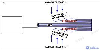
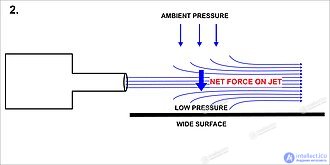
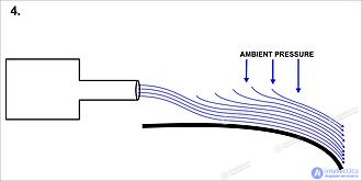
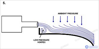
A free air jet entrains air molecules from its immediate surroundings, forming an axisymmetric low-pressure "tube" or "sleeve" around the jet (see Diagram 1). The resulting forces of this low-pressure tube ultimately balance any instability of the transverse flow, which stabilizes the jet in a straight path. However, if a solid surface is located close to the jet and approximately parallel to it (Diagram 2), then the entrainment (and hence removal) of air between the solid surface and the jet causes the air pressure on that side of the jet to drop, and this cannot be balanced as quickly as the low-pressure region on the "open" side of the jet.
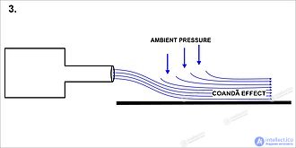
The pressure difference across the jet causes it to deflect towards the nearby surface and then attach to it (Diagram 3). The jet attaches even better to curved surfaces (Diagram 4), because every (infinitesimal) gradual change in the direction of the surface renews the effect of the initial bending of the jet. If the curvature is not too sharp, the jet can remain attached to the surface even after flowing around a cylindrically curved surface through 180° and thus moving in the opposite direction. The forces that cause these changes produce an equal and opposite force on the surface along which the jet flows. These forces can be used to generate lift and other forms of motion, depending on the orientation of the jet and of the surface to which it attaches. A small "lip" on the surface at the point where the jet begins to flow around that surface (Diagram 5) increases the initial deflection of the jet's flow direction. This happens because a low-pressure vortex forms behind the edge, promoting the jet's dip towards the surface.
The Coandă effect can be induced in any fluid and is therefore equally effective in water and in air. A heated profile significantly reduces drag.
Early sources provide the theoretical and experimental information needed for a detailed explanation of this effect. The Coandă effect can occur along a curved wall in both a free jet and a wall jet .
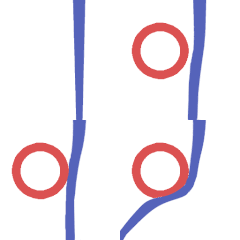
In the left-hand image of the previous section, "Mechanism of the Coandă effect", the effect described by T. Young as "the lateral pressure which facilitates the bending of an air stream near an obstacle" is that of a free jet, emerging from an orifice, with an obstacle in the surroundings. It involves the tendency of a free jet emerging from an orifice to entrain fluid from the restricted-access surroundings, without producing any regions of reduced pressure when there is no obstacle in the surroundings, as happens on the opposite side, where turbulent mixing takes place at atmospheric pressure.
In the right-hand image, the effect appears along a curved wall in the form of a wall jet . The image on the right shows a two-dimensional wall jet between two parallel flat walls, where the "obstacle" is a quarter-cylinder section following a flat horizontal rectangular orifice, so that no fluid at all is entrained from the surroundings along the wall, but only from the opposite side, in turbulent mixing with the ambient air.
To compare experiment with a theoretical model, consider a two-dimensional plane wall jet of width ( h ) along a circular wall of radius ( r ). The wall jet follows a flat horizontal wall of, say, infinite radius, or more precisely a radius equal to that of the Earth, without flow separation, because the surface pressure, as well as the external pressure in the mixing zone, is everywhere equal to atmospheric pressure, and the boundary layer does not separate from the wall.
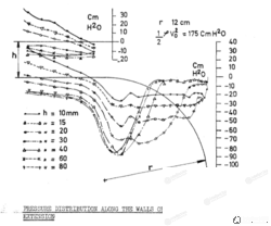
At a much smaller radius (12 centimeters in the image on the right), a transverse difference arises between the external pressure and the pressure at the wall side of the jet, creating a pressure gradient that depends on theh/rrelative curvature. This pressure gradient can arise in the zone before and after the start of the jet, where it builds up gradually, and can vanish at the point where the jet's boundary layer separates from the wall, where the wall pressure reaches atmospheric pressure (and the transverse gradient becomes zero) .
Experiments carried out in 1956 with turbulent air jets at a Reynolds number of 10⁶ and various jet widths ( h ) , show the pressure measured along the radius of the circularly curved wall ( r ), at a number of horizontal distances from the start of the jet (see the diagram on the right).
Above the critical value ofh/rratio of 0.5, only local effects are observed at the place where the jet forms, extending over a small angle of 18° along the curved wall. The jet then immediately separates from the curved wall. Thus the Coandă effect is not observed here, but only a local attachment: a sub-atmospheric pressure appears on the wall over a distance corresponding to a small angle of 9°, followed by an equal angle of 9° over which this pressure rises to atmospheric pressure as the boundary layer, subjected to this positive longitudinal gradient, separates. However, if theh/rratio is less than the critical value of 0.5, the sub-atmospheric pressure measured on the wall at the start of the jet is maintained along the wall (up to its end; see the diagram on the right). This is the "true Coandă effect", because the jet attaches to the wall "at almost constant pressure", as in an ordinary wall jet.
A calculation carried out by Woods in 1954 for inviscid flow along a circular wall shows that an inviscid solution exists for any curvature h/r and for any given deflection angle up to the separation point on the wall, where a singular point appears with an infinite slope of the surface pressure curve.
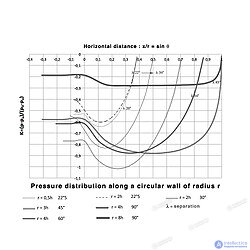
The calculation uses the separation angle obtained in the earlier experiments for each value of the relative curvature h/r. The image here was obtained recently and shows inertial effects , represented by the inviscid solution: the calculated pressure field is similar to the experimental one described above, outside the nozzle. The curvature of the flow is caused solely by the transverse pressure gradient, as described by T. Young. In this case viscosity produces only a boundary layer along the wall and turbulent mixing with the ambient air, as in an ordinary wall jet, except that this boundary layer is peeled off by the difference between the final ambient pressure and the lower surface pressure along the wall. According to Van Dyke , as cited in Lift, the derivation of his equation (4c) also shows that the contribution of viscous stress to the turning of the flow is negligible.
An alternative approach might be to calculate the deflection angle at which the boundary layer, subjected to the inviscid pressure field, separates. An approximate calculation was attempted that yields the separation angle as a function ofh/rand the Reynolds number: The results are shown in the image; for example, 54° was calculated versus 60° measured forh/r= 0.25. It would be desirable to carry out more experiments and a more accurate boundary layer calculation.
Other experiments, carried out in 2004 using a wall jet along a circular wall, show that the Coandă effect does not occur in laminar flow , and that the critical value of theh/rratio for low Reynolds numbers is much lower than for turbulent flow. down to h/r= 0.14 at a Reynolds number of 500 andh/r= 0.05 at a Reynolds number of 100.
L. C. Woods also carried out a calculation of the inviscid two-dimensional flow of a free jet of width h, deflected around a cylindrical surface of radius r, between the first contact A and separation at point B, including the deflection angle θ . Again a solution exists for any value of the relative curvature h/rand angle θ. Moreover, in the case of a free jet the equation can be solved in closed form, yielding the velocity distribution along the circular wall. The surface pressure distribution is then calculated using the Bernoulli equation. Denote the pressure ( pa ) and velocity ( va ) along the free streamline at atmospheric pressure, and γ — the angle along the wall, equal to zero at point A and θ at point B. Then the velocity (v) will be:

An image of the surface pressure distribution of a jet around a cylindrical surface, using the same values of relative curvature h/r , and the same angle θ, as found for the wall jet shown in the image on the right, has been established: it can be found in reference (15), p. 104 [ citation needed ] , and the two images are quite similar: the free-jet Coandă effect is inertial, the same as the wall-jet Coandă effect. However, an experimental measurement of the corresponding surface pressure distribution is not known.
The 1959 experiments of Bourque and Newman concerned the reattachment of a two-dimensional turbulent jet to an offset parallel plate after the formation of a separation bubble in which a low-pressure vortex is confined (as in image 5 of the previous section), and also a two-dimensional jet followed by a single flat plate inclined at an angle, instead of the circularly curved wall in the diagram on the right describing the wall-jet experiment here: the jet separates from the plate, then bends towards the plate as ambient fluid is entrained and the pressure drops, and finally reattaches to it, forming a separation bubble. The jet remains free if the angle is greater than 62°.
In the latter case, namely in the geometry proposed by Coandă, the inventor claims that the quantity of fluid entrained by the jet from the surroundings increases when the jet is deflected, which is used to improve the scavenging of internal combustion engines and to increase the maximum lift coefficient of a wing, as indicated in the application examples below.
In both cases the surface pressure distribution and the reattachment distance were properly measured, and two approximate theories were developed for the mean pressure inside the separation bubble, the reattachment position and the increase in volumetric flow rate from the orifice: agreement with experiment was satisfactory.
The Coandă effect is used in various high-lift devices on aircraft , where air moving over the wing can be "bent down" towards the ground by flaps and by a jet flow blowing over the curved surface of the upper side of the wing. The bending of the flow results in aerodynamic lift . The flow from a high-speed jet engine mounted in a nacelle above the wing produces increased lift by sharply increasing the velocity gradient in the shear flow within the boundary layer. In this velocity gradient, particles are thrown away from the surface, thereby reducing the pressure there. Following Coandă's work on applying his research, and in particular the work on his "lenticular aerodyne" , John Frost of Avro Canada also spent considerable time investigating the effect, which led to a series of "inside-out" hovercraft-type aircraft, from which air exited as a ring around the outside of the aircraft and was directed by "attachment" to a flap-like ring.
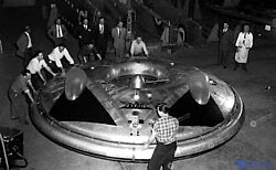
This differs from the traditional hovercraft design, in which air is fed into a central zone, the plenum , and directed downwards by a fabric "skirt". Only one example of Frost's design was built: the Avro Canada VZ-9 Avrocar .
The Avrocar (often designated "VZ-9") was a Canadian vertical take-off and landing (VTOL) aircraft developed by Avro Aircraft Ltd. as part of a secret US military project carried out in the early years of the Cold War . [ 20 ] The Avrocar was intended to use the Coandă effect to produce lift and thrust from a single "turborotor" blowing exhaust gases out over the rim of a disc-shaped aircraft, which was expected to provide VTOL-like performance. In the air it would have resembled a flying saucer . Two prototypes were built as "proof-of-concept" test vehicles for a more advanced US Air Force fighter, and also for a US Army requirement for a tactical combat aircraft. [ 21 ]
Project 1794 by Avro (1956) for the US military was a larger flying saucer based on the Coandă effect and intended to reach speeds of Mach 3 to 4. [ 22 ] The project documents remained classified until 2012.
The effect was also exploited in the US Air Force's Advanced Medium STOL Transport (AMST) programme. Several aircraft, notably the Boeing YC-14 (the first modern type to use the effect), the NASA Quiet Short-haul Research Aircraft and the Asuka research aircraft of Japan's National Aerospace Laboratory, were built to use the effect by mounting turbofan engines on the upper surface of the wings to provide a high-speed airflow even at low flight speeds. To date, however, only one aircraft has gone into series production making substantial use of this system: the Antonov An-72 . The Shin Meiwa US-1A flying boat uses a similar system, but directs the airflow from its four turboprop engines onto the upper surface of the wing to generate lift at low speeds. A more unusual feature is a fifth turboshaft engine inside the centre section of the wing, intended solely to supply airflow for powerful blown flaps . The addition of these two systems gives the aircraft impressive short take-off and landing capabilities.
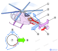
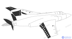
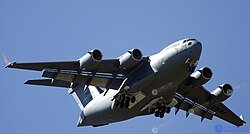
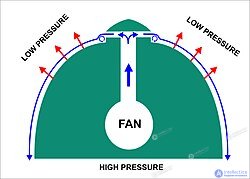
The experimental McDonnell Douglas YC-15 and its production counterpart, the Boeing C-17 Globemaster III , also use this effect. In the NOTAR helicopter the conventional tail rotor is replaced by a tail boom that uses the Coandă effect (diagram on the left).
A deeper understanding of the Coandă effect was provided by the scientific literature produced within the EU FP7 project ACHEON. This project used a special symmetric nozzle to model the Coandă effect efficiently, and identified innovative STOL aircraft configurations based on this effect. This activity was extended by Dragan in the turbomachinery sector, with the aim of better optimizing the shape of rotating blades, as part of the work of the Romanian Comoti research centre for turbomachinery.
A practical application of the Coandă effect is the use of inclined hydropower screens , which separate debris, fish and so on that would otherwise enter the flow reaching the turbines. Owing to the inclination, debris falls off the screens without mechanical cleaning, and because the screen wires optimize the Coandă effect, water flows through the screen to the penstocks that supply water to the turbines.
The Coandă effect is used in dual-mode fluid dispensers in automotive windshield washers.
The operating principle of oscillatory flowmeters is also based on the Coandă phenomenon. The incoming fluid enters a chamber containing two "islands". Because of the Coandă effect, the main flow splits and passes under one of the islands. This flow then returns to the main flow, causing it to split again, but in the direction of the second island. This process repeats as long as fluid circulates in the chamber, resulting in a self-sustained oscillation that is directly proportional to the fluid velocity and, therefore, to the volume of substance flowing through the meter. A sensor picks up the frequency of this oscillation and converts it into an analog signal indicating the volume of substance passing through.
In air-conditioning systems the Coandă effect is used to increase the throw of a ceiling diffuser . Because the Coandă effect makes the air leaving the diffuser "stick" to the ceiling, it travels a greater distance before dropping, at the same flow velocity, than if the diffuser were installed in free space, with no adjacent ceiling. A lower flow velocity means a lower noise level and, in the case of variable air volume (VAV) air-conditioning systems, permits higher turndown ratios . Linear and slot diffusers , which have a greater length of contact with the ceiling, exhibit a more pronounced Coandă effect.
In cardiology the Coandă effect explains the separation of blood streams in the right atrium of the fetus . It also explains why eccentric mitral regurgitation jets are attracted to and spread along adjacent surfaces of the left atrial wall (so-called "wall-hugging jets", as seen on Doppler echocardiography). This is of clinical importance because the visual area (and therefore the severity) of these eccentric wall-hugging jets is often underestimated compared with the more obvious central jets. In such cases, volumetric methods, such as the proximal isovelocity surface area (PISA) method , are preferred for quantifying the severity of mitral regurgitation.
In medicine the Coandă effect is used in mechanical ventilators.
In meteorology the theory of the Coandă effect has also been applied to certain airflows coming off mountain ranges, such as the Carpathians and the Transylvanian Alps , where effects on agriculture and vegetation have been noted. The effect apparently also occurs in the Rhône valley in France and near the Big Delta in Alaska.
In Formula One racing the Coandă effect was used by the McLaren, Sauber, Ferrari and Lotus teams, following its first use by Adrian Newey (Red Bull team) in 2011, to redirect exhaust gases through the rear diffuser in order to increase downforce at the rear of the car. Because of rule changes introduced by the FIA from the start of the 2014 Formula One season , the use of the Coandă effect to redirect exhaust gases was eliminated, owing to the mandatory requirement that the car's exhaust system must have no bodywork elements intended to create an aerodynamic effect located directly behind it.
In fluidics the Coandă effect was used to create bistable multivibrators , in which the working flow (compressed air) attached to one of the curved walls, and control jets could switch the flow between the walls.
The Coandă effect is also used to mix two different fluids in a mixer.
Besides the many potential advantages of using the Coandă effect in engineering practice, its application can also give rise to drawbacks.
In marine propulsion systems, the efficiency of a propeller or thruster can be significantly reduced by the Coandă effect. The force acting on a vessel and produced by a propeller is a function of the velocity, volume and direction of the water jet leaving the propeller. Under certain conditions (for example, when the vessel is moving through the water) the Coandă effect changes the direction of the propeller jet, making it follow the shape of the ship's hull . The lateral force from a tunnel thruster in the bow of a vessel decreases rapidly with increasing forward speed. [ c ] The lateral thrust can disappear completely at speeds above about 3 knots. If the Coandă effect is applied to symmetrically arranged nozzles, resonance problems arise.

Comments