
Lecture 21 min.
Flutter (from the English word flutter, meaning "tremor, vibration") is a combination of self-excited, undamped bending and torsional self-oscillations of aircraft structural elements, chiefly the wing of an airplane or the main rotor of a helicopter. As a rule, flutter appears when a certain critical speed is reached, which depends on the characteristics of the aircraft structure; the resulting resonance can lead to its destruction. The transition to supersonic speeds was complicated by the dangers of flutter.
Flutter is a self-oscillation of a solid body, or of a system of mechanically coupled solid bodies, in a flow of a continuous medium (that is, a liquid or a gas), together with that medium. This is what distinguishes flutter from other kinds of self-oscillation occurring in continuous media, in which the solid bodies remain stationary, at least at the initial stage and in theoretical models of these processes. As in any self-oscillating process, flutter must have a positive feedback mechanism that ensures the transfer of energy to it from the surrounding medium. According to the type of this mechanism, one can distinguish bending-torsion flutter, "multi-link" flutter (in aviation its most typical variant is called bending-aileron flutter) [20], and stall flutter.
Meanings of the term flutter
Related concepts
Self-oscillations are undamped oscillations in a dissipative dynamical system with nonlinear feedback, sustained by the energy of a constant, that is, non-periodic, external action.
Self-oscillations differ from forced oscillations in that the latter are caused by a periodic external action and occur at the frequency of that action, whereas the onset of self-oscillations and their frequency are determined by the internal properties of the self-oscillating system itself.
The term self-oscillations (avtokolebaniya) was introduced into Russian terminology by A. A. Andronov in 1928.
Buffeting (from the English buffet, "to strike, to beat") is a type of self-oscillation consisting of forced oscillations of the entire structure or its parts, caused by the periodic shedding of turbulent vortices from structural elements located upstream as the flow passes around them.
For aircraft, buffeting most often appears as sharp, unsteady oscillations of the tail unit caused by aerodynamic impulses from the wake of air behind the wing.
The shimmy effect (wobbling) (English: wobble, speed wobble, tank-slapper, death wobble ) is the onset of rapid oscillations (at a frequency of 4-10 Hz), usually in the steering wheels of a vehicle. At the moment shimmy begins, the vehicle as a whole is not affected by the oscillations, but as their amplitude grows, control is lost because of increasing yaw. In theory, the threat of shimmy exists for any vehicle with a single point of application of the steering input and a sufficient degree of steering-wheel freedom, for example motorcycles, bicycles and skateboards, as well as light tricycle-gear airplanes capable of reaching speeds above 80 km/h on the ground. On most cars the shimmy effect does not manifest itself significantly. The instability preceding the onset of the effect usually arises at high speeds and, by feel, roughly corresponds to the characteristic oscillations of shopping-cart wheels or the behavior of an aircraft landing gear during touchdown
The cause of flutter is usually the mismatch between the center of stiffness and the center of pressure, together with insufficient stiffness of the wing structure.
Flutter research in Russia began in the mid-1930s. Soviet aviation ran into the fact that when speed increased, at some critical value of it, airplanes began to shake violently and broke up in the air. The vibration grew so quickly that the pilot had no time to reduce speed. Only a matter of seconds passed from the onset of vibration to the destruction of the aircraft.
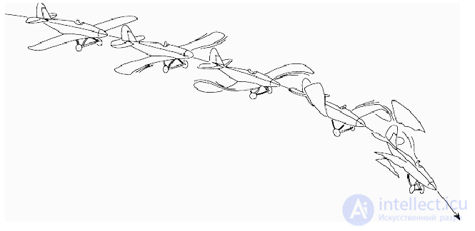
Many mathematicians racked their brains over the phenomenon of flutter. A huge contribution to solving the problem was made by E. P. Grossman and M. V. Keldysh. A whole series of experiments was conducted, a number of theoretical studies were carried out, and practical methods were developed to eliminate vibration at any flight speed. The main result of the work carried out in the USSR in 1934-1941 was the elimination of the danger of wing and tail-surface flutter. Relying on Keldysh's research, aircraft designers got rid of flutter, and the lives of many pilots were saved.
M. V. Keldysh, while working on the problem of nonlinear analysis of mathematical models of flutter suppression in aircraft control surfaces, used the harmonic balance method and noted that "we do not give a rigorous mathematical proof of all the propositions relating to this, and a number of conclusions we will build on intuitive considerations" . Subsequent development of the theory of absolute stability, the theory of differential inclusions, and analytical and numerical methods for their analysis, which were unavailable to Keldysh at the time of his work, now makes it possible to carry out a rigorous analysis of stability and of the onset of hidden oscillations in Keldysh's models .
Types of flutter depending on the presence of displacements and vibration of the control surfaces:
Types of flutter depending on the element subject to displacement and deformation:
Depending on which structural elements are subject to displacement and deformation, many types of flutter are distinguished, including:
1) Wing bending-torsion (the wing bends and twists),
2) Bending-aileron (the wing bends, the aileron deflects),
3) Torsion-aileron (the wing twists, the aileron deflects),
4) Bending-aileron-trim-tab (the wing bends, the aileron and trim tab deflect),
5) Servo-compensator,
6) Chordwise flutter of helicopter main rotor blades.
Wing flutter can arise under the action of some force (aileron deflection, a gust of wind) that causes the wing to deflect, through bending, from its initial (neutral) position 1 (from the plane 0XZ), for example upward. Striving to return to the initial position under the action of elastic forces, the wing begins to move downward (2) not plane-parallel but with twisting, because the positions of the center of pressure (where the lift is applied) and the center of mass (where the inertial and mass forces are applied) do not coincide with the center of stiffness (about which the wing twists).
Overshooting the neutral position by inertia, the wing deflects downward (3, 4), and the pattern repeats with the signs of all forces and moments reversed.
The phases of this motion and the corresponding bending-torsion ( – bending and
  – torsional) deformations of the wing over one oscillation cycle relative to the initial position (the plane 0XZ) are illustrated in the figure.
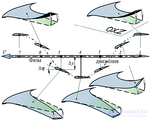
Fig. Illustration of the aircraft wing flutter phenomenon
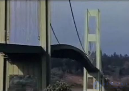
Bridge flutter
In bending-torsion flutter, positive feedback is realized if the line of the body's centers of inertia lies downstream of the line of centers of stiffness, which, in the absence of special measures, is a typical situation for bodies such as an airplane wing. Then, during bending oscillations of the wing, it twists in such a way that the additional aerodynamic force on it caused by the torsion acts in the same direction in which the wing moves during its stroke, reinforcing it. Thus these bending strokes grow exponentially, amplifying themselves until the wing fails [20].
In "multi-link" flutter, a system of at least two mechanically coupled solid bodies takes part; in practice, usually a wing and an aileron, a separate small aerodynamic surface located behind the main wing. Here, unlike in buffeting, there are no appreciable spatial gaps between the bodies of the oscillating system under consideration (the aileron, unlike, say, the tail unit, is located directly on the wing). In this case the torsion of the wing is no longer necessary, and the source of positive feedback is the aileron itself, moving relative to the wing so as to create an additional aerodynamic force of the wing-aileron system in the direction of the wing's stroke [20]. In other respects the positive feedback mechanism is the same as in the previous type of flutter. Both of these types of flutter occur on well-streamlined bodies, when there is no need to include the viscosity of the continuous medium in the basic mathematical model of the phenomenon, and the solution is sought for an inviscid potential flow (potential everywhere except at singular points, whose number equals the number of bodies in the oscillating system).
Unlike the types of flutter briefly described above, the viscosity of the flow is of fundamental importance for the onset and development of stall flutter, which occurs on poorly streamlined (bluff) bodies. It is precisely because of the action of viscosity that periodic vortex structures arise in the flow behind such bodies, called Karman vortex streets in honor of the outstanding aerodynamicist of the twentieth century Theodore von Karman, who built the first adequate mathematical model of this phenomenon 98 years ago. The Karman vortex streets themselves can be observed, with simple visualization methods and sometimes even without them, behind practically any obstacle in the path of a flow, whether of air or water (see, for example, photograph 94 from source [21] in Fig. 6, obtained for water flowing around a circular cylinder).
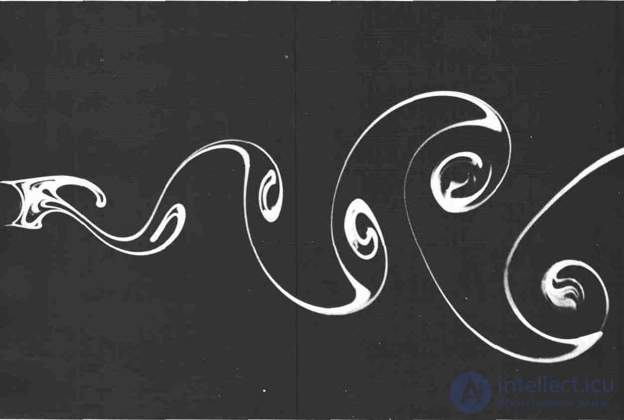
Fig. 6
The positive feedback mechanism in the self-oscillation of bodies that create such vortex streets is provided by the fact that the body's oscillations intensify vortex formation, which in turn increases the forces and moments acting on the body and, consequently, its oscillations [22]. Unlike in bending-torsion flutter, the mechanism of cross-coupling between the translational and torsional motions of the body's elements does not play an essential role here, so stall flutter can be practically purely bending (see Fig. 7, which schematically shows the Karman vortex street in the vicinity of a body modeling the superstructure of a bridge).
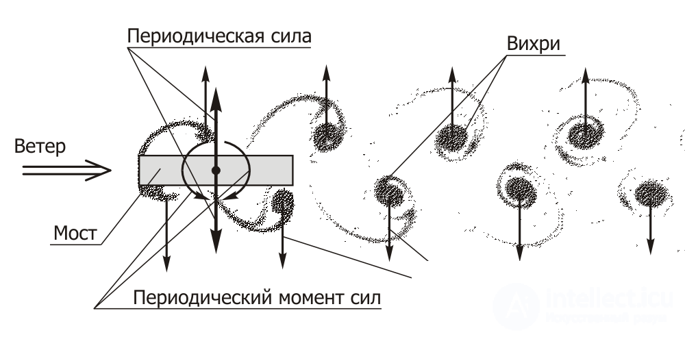
Fig. 7
In stall flutter, in addition to the lift force perpendicular to the direction of the oncoming flow, the body is also acted upon by the aerodynamic drag force directed along the flow. Besides a constant component, the drag force also has an oscillating vortex component, whose frequency is twice the frequency of the vortex lift force. The frequency difference arises because the frequency of the lift force is determined by the spacing between vortices along only one side of the Karman street, while the frequency of the periodic component of the drag force is determined by the spacing between vortices along both of its sides [22]. The variable component of the drag force is usually small compared with the lift force and, therefore, is not shown in Fig. 7 for simplicity.
For our purposes there is no need to go into all the subtleties of stall flutter; it is enough to use the main results of the theory of this phenomenon. The vortex shedding frequency νv in such flutter, which is the excitation frequency νp of the system's self-oscillations, is calculated as follows:
(1)
where St is the Strouhal number (a dimensionless similarity parameter), v is the flow velocity, and d is the transverse dimension of the bluff body. In essence, formula (1) is the definition of the Strouhal number, and therefore, it would seem, it cannot serve as a working tool for any calculations.
However, such separated flows have a remarkable property: over a very wide and practically interesting range of the parameters governing the process, the Strouhal number for a given body shape remains almost constant. Moreover, even where this number is not constant, it depends on only a single dimensionless combination of them, the similarity parameter called the Reynolds number Re:

where ρ is the density of the continuous medium and μ is its dynamic viscosity coefficient. Fig. 8, borrowed from source [23], shows the dependence of the Strouhal number St on the Reynolds number Re as the latter varies from 3·101 to 3·105 for flow around a circular cylinder placed across the flow.
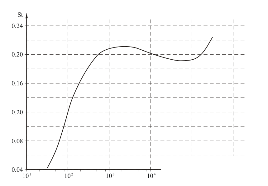
Fig. 8
The graph shows that for Reynolds numbers 3·102 < Re < 3·105 the Strouhal number is St = 0.20 ± 0.02. At a wind speed of 10-20 m/s and an air temperature of about 290 K, these values of the similarity parameter correspond to a cylinder diameter from 0.2 mm to 0.5 m (see [24, 25]), which covers the entire range of sizes from the wires of measuring instruments and the strings of an "Aeolian harp" to the thickest stay cables of suspension bridges. At Reynolds numbers 5·105 < Re < 5·106 the vortex street behind a circular cylinder becomes strongly turbulent, so that the Strouhal number becomes impossible to determine. Then, at Re > 5·106 the Strouhal number stabilizes again and turns out to be St ≈ 0.3 [22]. All this refers to the excitation frequency of oscillations directed perpendicular to the flow velocity, that is, the frequency of the vortex lift force. If it is necessary to calculate the usually much weaker oscillations along the flow velocity vector, a factor of 2 should be introduced into the numerator of formula (1).
There is one more property of the Strouhal number in stall flutter, which may be even more useful for solving the task at hand, namely calculating the excitation frequency of oscillations when wind blows over bridges. This property is that the Strouhal number also depends rather weakly on the shape of the body's cross-section, especially if the body surface has edges that fix the position of the separations that generate the vortices. From Karman's classical solution, derived for a flow that is inviscid everywhere except at two points on the body and obtained by taking the limit in the Reynolds number, it follows that for a circular cylinder the Strouhal number is St ≈ 0.20 [26]. The graph in Fig. 8 shows that this value agrees well with experimental data at 3·102 < Re < 3·105. Besides the cylinder, Karman considered the flow around one more body, a flat plate set across the flow [26]. For it, processing of calculation and experimental results led to a Strouhal number of St ≈ 0.145. If the cross-section of the body is a square, the Strouhal number for it will be practically the same as for the plate, St ≈ 0.14 [27].
The only qualitative difference in the dependences St = f(Re) under consideration for a plate or a body with a rectangular-type cross-section that can be predicted immediately is that the critical Reynolds number at which the strongly turbulent zone begins, where the Strouhal number cannot be determined, will be considerably larger than for a circular cylinder, if such a boundary exists for them at all. This prediction stems from the fact that at a critical Reynolds number Re* ≈ (1.5-3)·105, for flow around a three-dimensional body whose cross-section coincides with a circular cylinder, a phenomenon arises that bears directly on the separated flows under consideration. This phenomenon is called the drag crisis of a sphere [28]. It is usually described as a sharp drop in the aerodynamic drag of the sphere and is caused by a rapid but unstable contraction of the vortex separation points from the peripheral regions of the sphere's surface closer to its axis parallel to the oncoming flow, owing to the displacement of the boundary layer separation points. In this case, conditions with relatively low initial flow turbulence correspond to the upper limit of the critical Reynolds numbers, Re* ≈ 3·105.
A similar drag crisis, at somewhat higher critical Reynolds numbers, also occurs for flow around a circular cylinder. From this one can conclude that it is the drag crisis that leads to strong turbulization of the Karman vortex street behind the cylinder at Re* ≈ 5·105. In the new vortex configuration the street loses stability, and at Re ≥ 5·105 a so-called turbulent wake forms in its place. As already mentioned, unlike bodies with smooth surfaces, on bodies with discontinuities of surface smoothness (edges) the vortices always shed from these edges regardless of the Reynolds number. Therefore, for both the plate and the body whose cross-section is shown in Fig. 7, the vortex shedding points always keep their fixed position, and the zone of definite and stable Strouhal number values should consequently extend to considerably higher Reynolds numbers, possibly up to an overlap with the next stability zone, which begins somewhere in the vicinity of Re ~ 107.
From the vortex street stability condition obtained in Karman's theory, it follows that there is a single fixed ratio between the transverse spacing h and the longitudinal spacing L between vortices [26]:
 (2)
(2)
whence

For a staggered arrangement of the rows, when each vortex of the upper row is located exactly midway between the nearest vortices of the lower row, and vice versa (see Figs. 6, 7), the velocities u of the rows' motion relative to the flow will be [26]
 (3)
(3)
Here Γ is the circulation of these vortices.
The vortex frequency is
 (4)
(4)
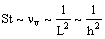
and the Strouhal number is proportional to the frequency νv. Then, from formulas (1)-(4), for a given body shape and given flow velocity and circulation, it follows that
 (5)
(5)
Formula (5) explains the increase of the Strouhal number for the Karman street forming on a circular cylinder at Re > 5·106. In this case the boundary layer on the body surface becomes fully turbulent, and therefore its separation points from the surface, where the vortices originate, turn out to be closer to its longitudinal axis (parallel to the velocity vector of the oncoming flow) than in a laminar boundary layer at 3·102 < Re < 3·105 [28]. This causes the distance h between the sides of the Karman street to decrease as well, and its Strouhal number grows from St ≈ 0.2 to St ≈ 0.3. A reduction in the street width of only ~20% is sufficient for this.
The difference between the Strouhal numbers for flow around a circular cylinder and around a plate set across the flow also becomes understandable. Vortices are shed from the edges of the plate, but not from the extreme transverse points of the surface of a circular cylinder; rather, they are shed from points on its surface located closer to its longitudinal axis (see Fig. 6). The Reynolds number of the flow shown in this figure is Re = 140, so for the cylinder St ≈ 0.17 (see Fig. 8). This means that, for equal transverse dimensions of the cylinder and the plate, the initial width of the vortex street behind the cylinder, and correspondingly the width established at some distance from the obstacle, should be about 10 percent smaller, and the Strouhal number correspondingly about 20 percent higher (the influence of the velocity difference on the Strouhal number is much weaker and can be neglected in this case). It can be seen that the vertical distance of the vortex formation points from the longitudinal axis of the cylinder in Fig. 6 is indeed approximately 90% of its radius.
Let us now consider the formation of a Karman street on a body with flat faces that is infinitely long in the longitudinal direction, as if the body shown in Fig. 7 continued to the right to infinity. Vortices always originate at the leading edges of this body, and the upper and lower sides of the Karman street are thereby separated by the body, while the vortices themselves pass along its lateral solid surfaces. In an inviscid continuous medium, the no-penetration boundary condition on a solid surface can, as is well known, be modeled by reflecting the flow singularities, which in the present case are vortices [26]. The reflection of the vortices must be made symmetrically with respect to this solid surface. Therefore, in the mathematical model describing the motion of vortices along it, a row of fictitious vortices appears, which together with the actually existing row in the flow forms a Karman street with a symmetric arrangement of vortices. And it is precisely the interaction of the vortices in each of these two new Karman streets that will determine their parameters.
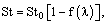
It is known that the symmetric arrangement of vortices is unstable [26]. This means that such vortex streets should "break up" soon after their formation, and, consequently, the Strouhal number for such a flow can be taken to be 0. It is natural to assume that for real bodies of rectangular cross-section the Strouhal numbers St will have values intermediate between the extreme values of St obtained above for the plate and the semi-infinite body. To estimate them, one can use a suitable interpolation formula built from some set of experimental data, whose parameter should be the ratio of the body's transverse length b to its height d:
 (6)
(6)
where St0 is the Strouhal number for a flat plate, λ is the body aspect ratio b/d, and f(λ) is a function satisfying the following conditions:
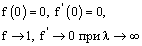 (7)
(7)
The condition that the derivative of the function f equals 0 at λ = 0 is introduced so that for 0 ≤ λ ~ 1 the Strouhal number depends only weakly on this parameter (which agrees with experimental data), and so that for λ >> 1 the function f(λ) approaches 0 asymptotically. For 1 < λ ~ 10 this function should give values reasonably close to the experimental ones.

Comments