Lecture
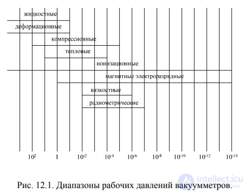
A universal method or means of measuring vacuum does not exist. When measuring pressure, they are based on various physical laws that are directly or indirectly related to the pressure or density of the gas. The SI unit of pressure is Newton per square meter (N / m 2). The ranges for measuring vacuum with various vacuum gauges are presented in Figure 12.1.
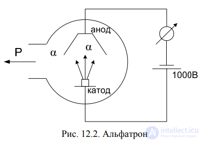
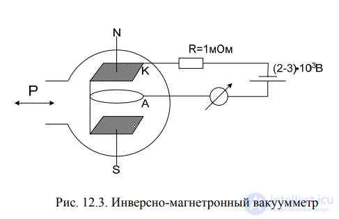
In electronic ionization vacuum gauges, ionization is carried out by a stream of electrons. To measure pressure up to 10-5 N / m 2 (10-7 mm Hg column), an ionization radioisotope vacuum gauge (alfatron) is used (see Fig. 12.2.). The magnetic electric-discharge vacuum gauge (see Fig. 12.3.) Allows the measurement of vacuum up to 10-12 N / m 2 (10-14 mm Hg column). It contains a plane-parallel cathode (K) of two plates and an annular anode (A), the plane of which is parallel to the cathode plates located in
flask (tube). The flask is located in a magnetic field with an intensity of H = 32 ka / m (400 e), the direction of the magnetic field is perpendicular to the plates.
If the mobility of its elements in force sensors is undesirable, then the previously described netziks cannot be used. Reliability and quality of control, control and regulation are increased if the measured mechanical quantity acts directly on the transducer (sensor), bypassing the intermediate links, i.e., when the sensitive element of the sensor and the transducer are one. 106 Such sensors include transducers based on the use of the magnetoelastic effect and the piezoelectric effect, i.e., magnetoelastic, magnetoanisotropic, and piezoelectric sensors.
The phenomenon of magnetostriction is known in which, under the action of an external magnetic field, the orientation of the material and the linear dimensions of the sample from the magnetized material change.
There is a phenomenon of reverse magnetostriction, this is a magnetoelastic effect. The magnetoelastic effect is the effect of a change in the magnetic properties of a material under the influence of mechanical deformations. Under the influence of elastic deformation, the shape of the crystal lattice of the ferromagnetic material and the orientation of the spontaneous magnetization vector Js in the lattice change. There is a relationship between the change in the size of the ferromagnetic body in the direction of the action of the external magnetizing field H and the change in the induction B under the influence of external mechanical stresses σ

The magnetic flux Φ = BS = 4πJsS, where S is the cross section of the sample. During tensile deformation of a ferromagnetic material in an external magnetic field H> Hs, the magnetic flux changes due to a change in the spontaneous magnetization Js, i.e.

Expressing dS / S in terms of the elastic modulus E, the mechanical stress σ, and the transverse dimensional change coefficient ε, we can write

Neglecting the deductible in view of the smallness of ε 2, we can write

This shows that the change in magnetic flux during deformation of a ferromagnetic sample depends on a change in its magnetization Js, mechanical properties, and dimensions.
As a result of mechanical stresses, for a given magnetic field strength H, the magnitude of the magnetic induction V.T. changes to. B = μH, then under the influence of mechanical stresses, at H = const, the magnetic permeability of the ferromagnet changes. The relative change in μ at mechanical stresses has a dependence

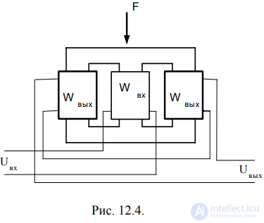
where λ0 is the initial magnetostriction. The effect of changing the magnetic properties of ferromagnetic materials from mechanical stresses under the action of an external force is used in magnetoelastic sensors (see Fig. 12.4.). In the sensor, several windings are wound around a closed magnetic circuit. The magnetic flux resistance is Rml / μS, where l and S are the length and cross section of the magnetic circuit. The inductance of the magnetizing coil is determined by L = w2 / zm, and E2 of the secondary winding is expressed as

where I is the magnetizing flux, f is the current frequency, ε is the shape factor of the magnetization reversal curve.
Sensitivity of such a sensor

is non-linear. Its advantages are high sensitivity (k≈200 for permalloy and k≈80 for technical steel) and high operational reliability, and the disadvantages are the presence of instability of characteristics and hysteresis loop. The anisotropy of the properties of ferromagnets is manifested in a significant difference in the cost of magnetization, depending on the direction of the external field relative to the spatial diagonal of the iron crystal. The iron crystal has the shape of a cube, along the edge of the cube [100] - magnetization is carried out with min costs, along the diagonal of the cube face [110] - the axis of average magnetization, magnetization is difficult, and along the spatial diagonal [111] - the axis of difficult magnetization, magnetization is with max costs.
Magnetostriction during magnetization  , this is anisotropy.
Hot rolled steel has insignificant anisotropy, and in cold rolled steel it is several times larger. Under the influence of external mechanical stresses, the magnetic properties of the material undergo changes in all directions with different intensities and with different signs depending on the external magnetic field, since the magnetic anisotropy of the material changes. A magneto-anisotropic sensor (see Fig. 12.5.) Is a rectangle of ferromagnetic material with four holes located on mutually perpendicular diagonals, where two windings fit into diagonally opposite holes.
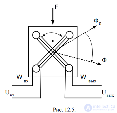
E. d. in the secondary winding is described by the expression

where: c is the coefficient of the shape of the magnetization reversal curve; q is the design factor depending on the size of the magnetic circuit and the distance between the holes; B - magnetic induction; S is the cross section of the magnetic circuit that determines the resistance to magnetic flux, α = f (F) is the angle between the direction of the magnetic flux and the plane of the coil w2
. To expand, in the direction of increasing load capacity, the industry released sensors made of cold-rolled electrical steel sheets in the form shown in Fig. 12.6., Where both windings are dispersed along the core package
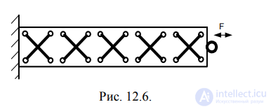
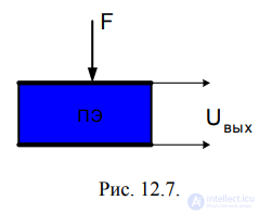
Such sensors are acceptable for monitoring static forces, for example, transport (auto and rail), since they work at F = n100 kg. 110 For direct measurement of elastic deformations, at F≤1.0 kg, piezoelectric sensors can be used (see Fig. 12.7.).
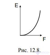
In them, under the action of elastic deformation forces, e is generated. d.s according to non-linear law (see Fig. 12.8.)
Typical force transducers according to fig. 7. represent quartz or piezoceramic washers (plates) coated with a method of burning silver with electrodes. Their advantages are small size and weight, and the disadvantages are that it is difficult to manufacture a sensor for loads F <10 H, when the diameter of the washer is greatly reduced, and the presence of charge draining (see Fig. 12.9).
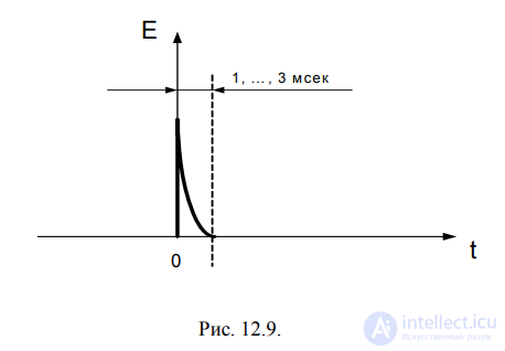
Although Cd≈10 pF, R leakage ≈1013 Ohm, fmin≈2 × 10⁻⁴ Hz, but the total sensor time constant is τ≈10-3 sec. Due to the draining of the charge, after 1 second, an error of 103 times takes place. The use of the direct piezoelectric effect ensures the full measurement of only dynamic and quasistatic forces, therefore these sensors are used to detect the presence of touch. To measure the forces in statics, a piezoelectric transformer is acceptable (see Fig. 12.10.), In which two electrodes are placed on one end of the washer and one on the other, the sensor is powered by an external AC voltage source Uin, the output signal is U = f (F), but U ≠ f (t)

To increase the sensitivity of the piezoelectric transformer, it is built according to the circuit shown in Fig. 12.11., I.e., the piezoelectric elements in it 112 are stacked through damping pads made of dielectric (shown in yellow), and electrically connected in series through current amplifiers.
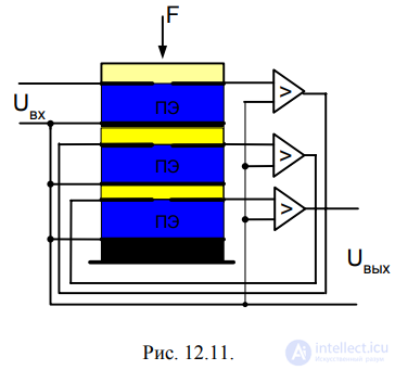
Such a sensor is acceptable for measurements at F≈0.01 g. It finds application in accurate weighing technology
Comments
To leave a comment
Sensors
Terms: Sensors