Lecture
2.1. Classification and selection of pressure sensors
In the control system of the boiler, temperature control is necessary. In this case, it is necessary to take into account the dynamic pressure of the heating steam in the pipeline. For this purpose, a steam pressure sensor is used.
Currently, there is a wide variety of pressure sensors, therefore, using the classification method, we will compile a classification of pressure sensors.
The classification of pressure sensors is presented in Figure 2.1.
WITH 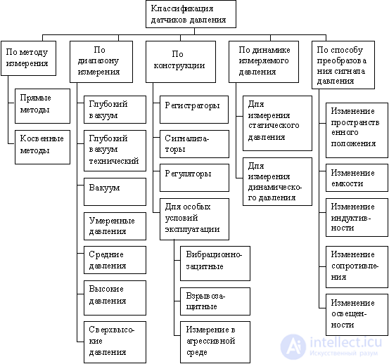 chemically, this classification is as follows:
Figure 2.1. Pressure Sensor Classification
By measurement method
a) direct methods
Pressure can be determined directly by changing the force acting on a given surface (direct method). Piston pressure gauges are based on this method in which the force acting on a piston with a known area is balanced by weights. A modification of such a pressure gauge is a liquid pressure gauge in which the measured pressure is determined by the height and specific gravity of the liquid column. Liquid and deadweight testers do not require calibration with reference pressure gauges, as their readings can be determined by measuring linear size and mass. When measuring high pressures, solidification points or phase transition points of various substances can be used as exemplary measures.
Liquid pressure meters are mainly used for measuring low pressures, but they can also be used to measure small pressure differences at high static pressure. As locking liquids, alcohol, water, mercury, or special liquids with a low vapor pressure are mainly used.
Cargo and piston pressure gauges measure the force developed by the measured pressure on a piston moving in a hollow cylinder. As a balancing force, a load, a spring force or an electromagnetic force is used. Instruments loaded with weights are called cargo gauges. The main field of application for pressure gauges is the medium pressure range.
b) indirect methods
In addition to the two named direct methods for measuring pressure, there are a large number of indirect methods based on the use of various laws of applied physics. Indirect mechanical methods of measuring pressure are based on determining the elastic deflection of the sensitive elements formed in a certain way under the influence of controlled pressure, as well as the compressibility of gases and liquids. In the field of measuring explosive pressures, a measure of the maximum pressure achieved can be plastic deformation of the sensing element, as well as electrical, optical and chemical phenomena that occur at certain pressures.
By measuring range
Currently, the range of pressures measured for scientific and applied purposes exceeds 18 orders of magnitude. Below is the absolute pressure scale. In brackets are pressure gauges corresponding to a certain measuring range.
a) deep vacuum (  bar). (Ionization pressure gauge)
b) deep technical vacuum (  bar). (McLead Pressure Gauge, Pirani Pressure Gauge)
c) vacuum (  bar). (Tubular quartz-glass springs, membranes, flat membranes, aneroid boxes, ring scales, bell manometers, mercury manometer, gas manometer, carbon washer manometer)
d) moderate pressure (  bar). (Metal tubular springs, flat membranes, aneroid boxes, piston pressure gauges, mercury pressure gauge, compressor pressure gauge, carbon washer pressure gauge)
d) average pressure (  bar). (Metal (copper) tubular springs, flat membranes, piston pressure gauges, differential piston pressure gauge, cascade pressure gauge, medium pressure compressor pressure gauge, pressure gauge with coal washers).
e) high pressures (  bar). (Steel tubular springs, piston pressure gauges for high pressures, differential piston pressure gauge, cascade pressure gauge, high pressure compressor pressure gauge, resistance pressure gauge).
g) ultrahigh pressures (  bar). (Steel tubular springs, high pressure compressor pressure gauge, resistance pressure gauge).
By design and purpose
a) recording devices
When moving the pen, greater friction must be overcome than when moving the arrow of the indicating device. Therefore, the working force developed by the elastic elements of the recording pressure gauges should be sufficiently large.
At the same time, the working effort is understood to mean the amount of work required to move the pen to full scale. The force required to overcome the friction should be only an insignificant part of the total effort developed by the sensing element. As sensitive elements, providing great working effort, apply wide helical or spiral tubular springs, multi-row aneroid boxes, as well as bellows. To transfer the angular displacement of the sensing element to the rectilinear moving pen of the recorder, elliptical mechanisms are used that provide, with an appropriate size ratio, proportionality between the indicated displacements.
b) pressure gauges with electrical signaling devices (signaling devices).
Alarm devices are designed to turn on and off electrical circuits depending on the position of the arrow of the indicating pressure gauge. Under normal operating conditions at moderate load, sliding contacts are applicable. With a small gap between the contacts there is a danger of the formation of an electric arc. In magnetic trigger contacts to exclude the formation of an arc, a permanent magnet is placed on the setpoint arrow, which brings the contacts together when a certain gap is formed between them. At the same time, such a magnet increases contact pressure. Signal contacts can be either normally open or normally closed. One of the varieties of contact pressure gauges is limit pressure transmitters, issuing an acoustic or optical signal at the outlet of pressure beyond the set limits.
c) pressure meters with remote transmissions (regulators).
In control circuits of various production processes, measuring and control equipment are usually combined on control panels. The output signals of the pressure sensor are transmitted pneumatically over short distances, electrically over significant distances. Various devices are used for remote transmission of pressure sensor readings: a rheostat converter in the form of a potentiometer, the slider of which is connected with the axis of the pressure gauge’s arrow; inductive, in which the ferromagnetic core connected with the needle of the pressure gauge, moving in the coil supplied with alternating voltage, changes its inductive resistance. For accurate measurements, bridge transmission schemes are used.
d) devices for special operating conditions;
Factors influencing the measurement process (vibration, acceleration, shock, temperature, etc.) can change the mechanical properties of the sensor and introduce errors that increase the error of the measured pressure. These factors can relate to both the work environment and environmental conditions. The action of factors such as constant vibration, an aggressive environment negatively affects the operation of the sensor, acting on it destructively. Therefore, the question often arises of using devices that have a certain protection, capable of working in special conditions.
- Measurement of highly pulsating pressures of the controlled medium and pressure measurement during vibrations of the controlled object.
In many areas of technology, it is necessary to control rapidly changing or fluctuating pressures; however, the measurement task does not include continuous monitoring of the specified process. Even in those cases when the sensitive element withstands the arising loads, jamming and wear of the transmission mechanisms are possible, accurate reading of readings is difficult. These phenomena are especially pronounced during pressure pulsations with a frequency approaching the natural resonance frequency of the pressure gauge.
- Explosion-proof pressure gauges for high pressure gases.
When measuring the pressure of compressed gases, the energy accumulated in the elastic sensing element contributes to the explosion. Oxygen is especially explosive in the presence of insignificant amounts of organic substances. Protection devices should exclude the possibility of ejection of individual parts (for example, the dial) in the direction of the front side of the device; this is necessary for personnel safety.
- Pressure measurement of aggressive media.
The sensitive elements of membrane pressure gauges are protected from aggressive media by introducing protective layers of stainless steel, tantalum, fluoroplastic, chemically pure silver, as well as by applying protective coatings, galvanizing and coating with lead and fluoroplastic. In other cases, separation devices are used in the form of membranes, thin-walled tubes of oval cross-section or bellows.
According to the dynamics of the measured pressure
Pressure sensors are characterized by the scope and reliability of their use in this area. Pressure is a process parameter and may change over time. It can be quasi-stationary or slowly changing in the case of static pressure, or more or less rapidly changing in the case of dynamic pressure. To track these changes, the sensor must have such properties as a high natural frequency, providing high speed; minimal inverse effect on the variable, to avoid distortion of pulsations on the surface of the sensing element.
a) instruments for measuring static pressure;
b) instruments for measuring dynamic pressure.
By a method of converting a pressure signal generated by a sensing element into a measured signal
There are countless ways to convert a pressure signal to any other signal. We list the most applicable and most common.
a) a change in spatial position.
This is one of the simplest and most obvious ways in the given classification. This method (in most cases) underlies the rest of the conversion methods. Pressure applied to the sensing element (membrane, Bourdon tube or membrane box) causes it to deform. Deformation leads to a change in the position of the movable part of the sensing element.
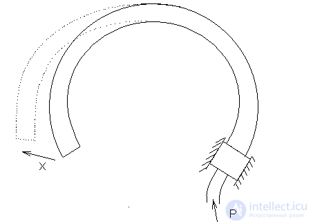
Figure 2.1.1.
b) resistance change
The sensing element is connected (with or without reduction gear) to the rheostat slider. A change in the measured pressure causes the moving part of the sensitive element to move, and, accordingly, a change in the position of the slider on the rheostat (Fig. 2.1.2.)
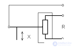
Figure 2.1.2. Resistance change
c) change in capacity
A sensitive element (for example, a membrane) is connected to one of the capacitor plates. The second capacitor plate is fixed. The change in pressure causes the moving end of the sensing element and the associated plate to move. Changing the distance between the plates leads to a change in the capacitance of the capacitor (Fig. 2.1.3.)
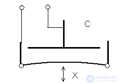
Figure 2.1.3. Capacity change
d) Change in inductance.
Through the core winding fixed motionless
pass electric current. The current creates an MDS, which generates a magnetic flux in the core, forming a contour between the core and the movable armature. An anchor is connected to a sensing element (e.g., a bellows). The change in pressure in the bellows leads to a displacement of the bottom of the bellows associated with the movable armature. Thus, a change in pressure leads to a change in the gap between the core and the armature, and, consequently, to a change in magnetic flux and inductance (Fig. 2.1.4.)
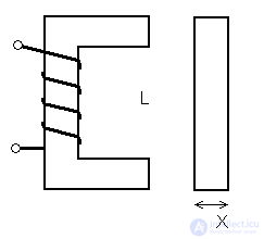
Figure 2.1.4. Change inductance
d) change in illumination
From the source through the hole, light falls on the receiver. The movable shutter is connected to a sensing element (for example, a Bourdon tube). Changing the pressure in the tube causes the valve to move along the hole. The position of the shutter determines the degree of illumination of the receiver (Fig. 2.1.5.)
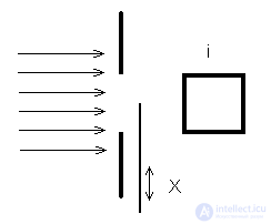
Figure 2.1.5. Light change
Device selection.
In accordance with the above classification, taking into account the operating conditions of the system, a sensor is selected. The steam pressure sensor must satisfy the following requirements :
- pressure measurement range from 0.1 to 0.7  ;
;
- the ability to measure in a dynamic environment;
- working environment - steam.
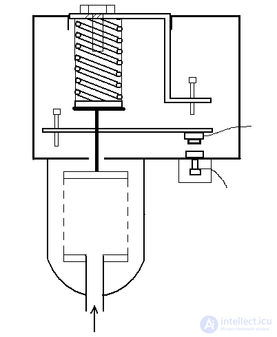
The selected pressure sensor is shown in Figure 2.1.6.
The main advantages of this device include high reliability, simplicity of design, comparatively cheap manufacturing, low inertia, and compliance with the requirements of the system in question (see above).
The disadvantages include a limited measurement range, reduced resistance to corrosion. It is not recommended to use in special operating conditions (with vibrations, in an aggressive environment).

 7
7


eight
5 6
4
3
2
1
Figure 2.1.6. Pressure sensor type DD.
The device and principle of operation.
The sensing element of the sensor is a bellows (1) balanced by a spring screw (2). When the pressure acting on the bellows changes, the stem (3) is mixed. When the pressure rises above a certain value, the switch lever (4) will move and the bridge (5) will move away from the contact (6). When the pressure drops below the minimum, under the action of a spring, the lever will move in the opposite direction, and the contacts will close. The setting of this sensor is carried out using the screw (7) and travel limiters (8) and (9) of the lever system. Processing medium - air, steam. The maximum allowable current through the contacts is not more than 5A, voltage 380V; working temperature  .
.
2.2. Calculation of pressure sensor type DD
The calculation of the pressure sensor consists in the calculation of the sensitive element. In the considered sensor, the sensing element is a welded bellows, that is, a bellows made by welding from ring plates (Figure 2.2.1.).
The bellows is a thin-walled cylindrical shell with transverse corrugation, capable of receiving significant displacements under the action of pressure or axial force. Thus, the bellows is designed to convert the measured pressure into force. Bellows are calculated using approximate formulas obtained from experimental data.
In instrumentation, bellows with a diameter of 8-10 to 120-150 mm with a wall thickness of 0.1-1.3 mm are used. Bellows are used in a wide pressure range: from hundredths to hundreds of atmospheres.
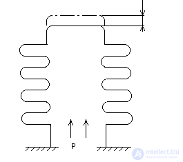
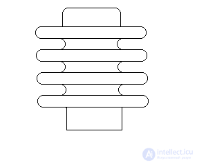
Figure 2.2.1. Welded bellows
Thus, the calculation of the sensor is reduced to determining the geometric parameters of the bellows and in the selection of the material of the bellows, in accordance with the specified requirements. This means that it is necessary to choose bellows parameters such that pressure p = 0.7  acting on the bellows caused the bellows ceiling to move
For stable operation of the system, the bellows must have high sensitivity. The bellows made by welding from ring plates (welding) have sufficient sensitivity. They are calculated by the following powerful formula: 
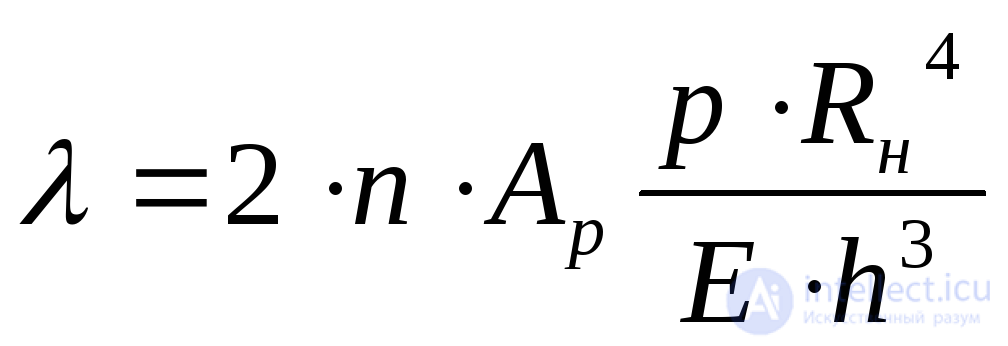 ,
,
Where  - axial deformation of the bellows, mm;
 - the number of working corrugations;
 - pressure acting on the bellows,
  ;
;
 - the outer radius of the bellows, mm;
 - the elastic modulus of the material from which the bellows is made;
 - wall thickness, mm;
 - ratio dependent ratio
 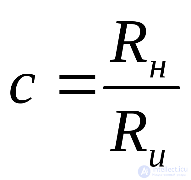 is determined by the table [2.4. since 195].
 - the inner radius of the bellows along the hollows of the corrugations, mm.
Using the selection method, following the requirements of the system in question, the following parameters are defined:
 ;
; 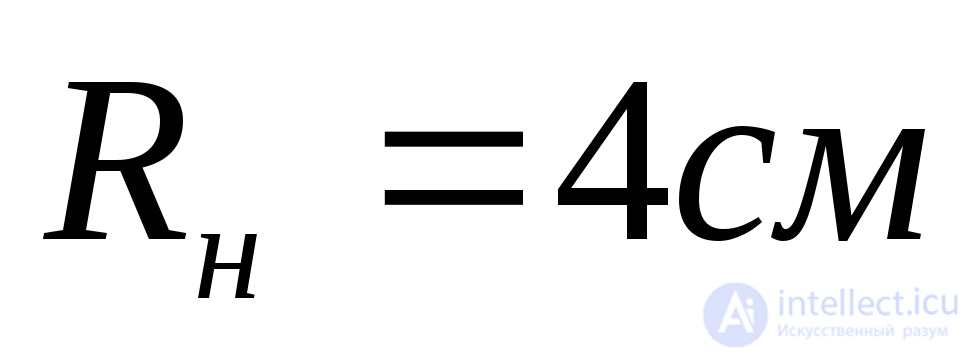 ;
;  ;
; 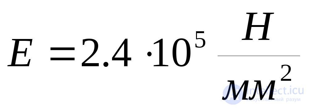 (corresponds to precipitation hardening alloys);
  .
.
2.3. Pressure sensor upgrade
The described sensor can be upgraded in two directions, namely:
a) modernization (improvement) of elements already existing in the sensor;
b) the introduction of new elements into the sensor that contribute to improving the performance of the sensor.
We restrict ourselves to improving the elements already in the sensor, since the introduction of new elements complicates the device of the sensor (and all ingenious is simple).
The sensitive element of the considered sensor is a welded bellows (see description above). A significant disadvantage of welded bellows is the reduced resistance to corrosion due to the presence of a large number of welds. To increase strength or corrosion protection, bellows are made multilayer. Also, for better corrosion resistance, you can replace the welded bellows with a seamless. (A bellows made of thin-walled seamless tubes is called Besshvov.) True, with such a replacement, the cost of the sensor increases - you have to pay for all the good.
Replacing the spiral return spring with a flat one allows eliminating unnecessary sensor elements: lever (4) of the switch, bridge (5), travel stops (8) and (9) of the lever system (see Fig. 2). Reducing the number of elements in the device increases the reliability of its trouble-free operation. The exclusion of the above elements allows to reduce the overall dimensions and weight of the sensor. The upgraded sensor is easier to implement both economically and technologically.
The pressure sensor upgraded by this method is shown in Figure 2.3.1.
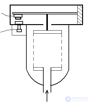
Figure 2.3.1. Upgraded pressure sensor.
Comments
To leave a comment
Sensors
Terms: Sensors