Lecture

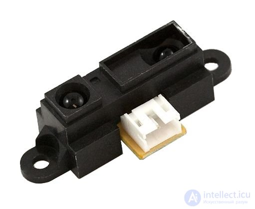
Sharp GP2Y0A21YK
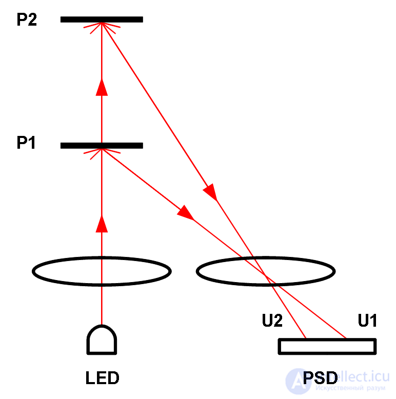
To measure the distance to the object, there are optical sensors that work on the method of triangulation. The most common of these are wavelength-based, infrared (in English, infra-red , abbreviated as IR) distance sensors with an output voltage produced by Sharp. Sharp sensors have an IR LED with a lens that emits a narrow light beam. The beam reflected from the object is directed through another lens to a position-sensitive photocell (in English, position-sensitive detector , abbreviated as PSD). The location of the beam incident on the PSD depends on its conductivity. Conductivity is converted to voltage and, for example, by digitalizing it with an analog-digital converter of a microcontroller, it is possible to calculate the distance. The figure below shows the path of the reflected beam at different distances.

The path of the light beam IR distance meter
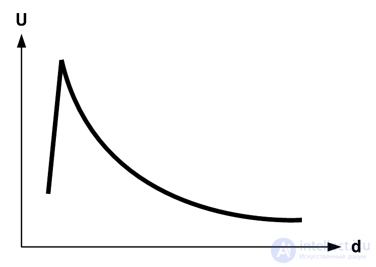
The output of the Sharp distance sensor is inversely proportional - as the distance increases, it decreases and grows slowly. The exact graph between the distance and the output is given in the sensor specification. The sensors, according to the type, have a measurement limit, within which the sensor output is reliable. Measuring the maximum real distance is limited by two aspects: a decrease in the intensity of the reflected light and the inability of the PSD to record a change in the location of the displayed small beam. When measuring distant objects, the output of the sensor remains approximately the same as when measuring the most distant distances. The minimum measurable distance is limited by the features of the Sharp sensor, namely, the output voltage at a certain distance (depending on the sensor: 4-20 cm) starts to fall sharply with decreasing distance. Essentially, this means that two distances correspond to one output voltage. Avoid getting too close to prevent problems.

Graph of voltage-distance typical Sharp IR distance meter
The Home Lab sensor kit includes an Sharp GP2Y0A21YK infrared distance meter with a measurement boundary of 10-80 cm. Sensor output voltage up to 3 V depending on the measured distance. The sensor is connected to the “Sensors” module and its output voltage is sent to channel 0 of the AVR analog-digital converter. Based on the previous task of the sensors, you can simply make a program that measures the output voltage of the distance meter, but in addition to this, the goal of this task is to familiarize yourself with the process of converting voltage to distance.
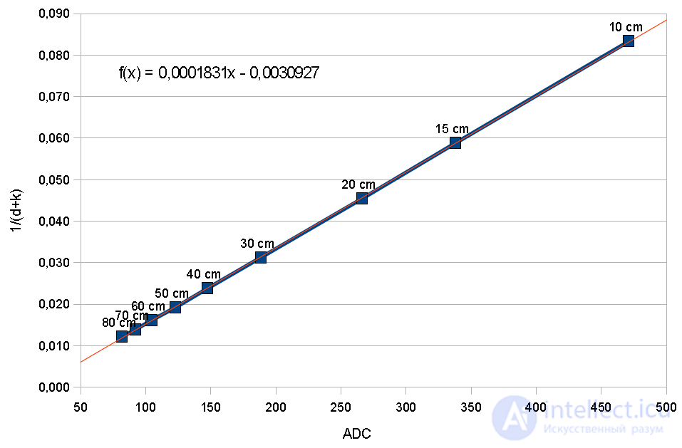
The specification of the GP2Y0A21YK sensor shows a graph of the relationship between the output voltage and the measured distance. This graph is not linear, but the graph of the reciprocal of the output voltage and distance is almost linear, and using it is quite simple to find a formula for converting voltage into distance. To find a formula, it is necessary to enter the points of this graph into any tabular data processing program and create a new graph from them. In the tabular data processing program, it is possible to automatically calculate the trend line on the basis of graph points. The following is a graph of the corrected inverse relationship between the output voltage GP2Y0A21YK and the distance together with the linear trend line. To simplify the formula, the output voltage has already been converted to a 10-bit value of an analog-digital converter with a reference voltage of +5 V.

Linearization of distance and ADC values
As can be seen in the graph, the trend line (blue) coincides quite accurately with the points of the graph (red line). Such a match is achieved using a distance correction constant. The correction constant was found by trial and error — different numbers were tried, until those with a graph covered by the trend line most were found. The correction constant for this graph is +2, i.e. 2. All the real distances in the graph are added. Since the graph is very similar to the linear trend line, you can make a generalization and say that the relationship between distance and voltage is as follows:
1 / (d + k) = a ⋅ ADC + b
Where
d - distance in centimeters
k - correction constant (found by trial and error)
ADC is the value of the digitalized voltage.
a is a linear term (the value comes out of the trend line equation)
b - free term (the value comes out of the trend line equation)
From the formula, you can express the distance d:
d = (1 / (a ⋅ ADC + B)) - k
In principle, this equation can calculate the distance, but this involves calculating a floating point, because fractional numbers are formed in the quotient. For a microcontroller operating with integers, it is necessary to simplify the formula and translate it into large factors. Dividing the formula into a linear term, we obtain the following form:
d = (1 / a) / (ADC + B / a) - k
Entering the value of the correction constant and the linear and free term obtained from the trend line equation into the formula, we obtain the formula for calculating the distance:
d = 5461 / (ADC - 17) - 2
This formula is calculated by 16-bit integers and is fully suitable for AVR. Before the calculation, you will have to make sure that the ADC value is above 17, otherwise you will divide by zero or a negative distance, which is not logical.
The following is the function of converting ADC values to centimeters recorded in the Home Lab library. The linear and free term, as well as the correction constant are not rigidly entered into the function, but they are specified by the objects of the structure parameter IR of the distance sensor. Saving the parameters separately in a constant, it is possible later just to add new models of IR distance sensors to the program.
 //
 // The structure of the parameters of the distance sensor IR
 //
 typedef const struct
 {
	 const signed short a;
	 const signed short b;
	 const signed short k;
 }
 ir_distance_sensor;

 //
 // Parameter object of the sensor GP2Y0A21YK
 //
 const ir_distance_sensor GP2Y0A21YK = {5461, -17, 2};

 //
 // Conversion of the ADC value of the IR distance sensor to centimeters
 // Returns -1 if the conversion failed
 //
 signed short ir_distance_calculate_cm (ir_distance_sensor sensor,
	 unsigned short adc_value)
 {
	 if (adc_value + sensor.b <= 0)
	 {
		 return -1;
	 }

	 return sensor.a / (adc_value + sensor.b) - sensor.k;
 }
To create a translation, you need to call the function ir_distance_calculate_cm whose first parameter is the parameter of the IR sensor object of the distance, and the second is the value of the ADC. The function returns the calculated distance in centimeters. If the calculation is incorrect (that is, if the ADC value is unnatural), the function returns -1. The use of an IR distance sensor and conversion function is demonstrated by the following program. An alphanumeric LCD screen is used where measurement results are displayed. If the distance is unnatural, a question mark is displayed.
 //
 // Example of a Home Lab distance sensor IR program.
 // LCD displays the measured distance in centimeters.
 //
 #include <stdio.h>
 #include <homelab / adc.h>
 #include <homelab / delay.h>
 #include <homelab / module / sensors.h>
 #include <homelab / module / lcd_alpha.h>

 //
 // Main program
 //
 int main (void)
 {
	 signed short value, distance;
	 char text [16];

	 // External sensor selection
	 pin ex_sensors = PIN (G, 0);
	 pin_setup_output (ex_sensors);
	 pin_set (ex_sensors);

	 // Setting the LCD screen
	 lcd_alpha_init (LCD_ALPHA_DISP_ON);

	 // Clear LCD Screen
	 lcd_alpha_clear ();

	 // The name of the program
	 lcd_alpha_write_string ("Distance Sensor");

	 // Configure the ADC converter
	 adc_init (ADC_REF_AVCC, ADC_PRESCALE_8);

	 // Endless cycle
	 while (true)
	 {
		 // Read the output voltage value of the sensor, rounded 4 times
		 value = adc_get_average_value (0, 4);

		 // Converting ADC value to distance
		 distance = ir_distance_calculate_cm (GP2Y0A21YK, value);

		 // Is it possible to display a distance or an error message?
		 if (distance> = 0)
		 {
			 sprintf (text, "% d cm", distance);
		 }
		 else
		 {
			 sprintf (text, "Error");
		 }

		 // Display text at the beginning of the second LCD line
		 lcd_alpha_goto_xy (0, 1);
		 lcd_alpha_write_string (text);

		 // pause
		 sw_delay_ms (500);
	 }
 }
Comments
To leave a comment
Sensors
Terms: Sensors