
Lecture
Object-oriented analysis
System dynamics, interaction diagrams, control channels, simulation
Action data flow diagram. The concept of process and control flows. Object access model
Dynamic behavior of objects, the concepts of states, events, state actions, life cycle.
Concept of information modeling. The concept of classes, attributes and relationships. Formalization of relationships.
Domain-level models, the concept of bridges, clients, servers.
Design – translation of the model into design documents using CASE tools.
Evolution. Writing code, testing, iterating — the OO approach thanks to recursive design, the system unfolds and grows more complex. Modification – evolving a finished product that has been delivered to the customer.
Advantages of recursive design during evolution:
Changes in the system, in order of worsening scenario:
The task of analysis – bring the model to a state where the interface will no longer need to be changed.
OO analysis
In structured programming the black box principle is used – we don't think about specific actions and data, but about what needs to be done. In OOP – the white box, data comes first of all. We identify the characteristics of objects, and only then arrive at how to process them.
The system is broken down into domains – interface, implementation, the task itself, service functions (for example communication) and so on. A domain diagram is drawn for the domain level of the whole task. To carry out the stages of analysis, a design matrix is drawn – we track which stages of analysis we have completed. A domain with more than 150 classes is hard to work with, and in practice – even with more than 50. Within a domain, groups of classes with many connections between them are clearly distinguished, while there are few connections between groups – the domain is split into subsystems, and we design the subsystems first, then implement the connections.
For the domain a subsystem connection model is built. Synchronous and asynchronous interaction schemes are distinguished, corresponding to the subsystem access model (synchronous) and the subsystem interaction model (asynchronous).
Object interaction model (OIM) – a graphical representation of the interaction between state models and external entities. (Built for each subsystem or domain).
The OIM is drawn as an oval, an external entity – a rectangle (called a terminator). Events generated by one model for another are drawn as an arrow – events from external entities can arrive the same way. Events can be directed toward terminators. The OIM is formed hierarchically – objects that are most aware of the whole system (active ones) are placed at the top of the diagram. If an event arrives from outside to an OIM located at the top, the terminators are drawn at the top – top-level terminators. If events leave or arrive at a lower-level OIM, the terminators are drawn at the bottom. There can be a top-level and bottom-level control scheme – the system is bounded by terminators from above or below. One should strive for the interaction of a terminator at the top level to come down to a single model. There is no such restriction at the bottom level – there can be any number of OIMs interacting with bottom-level terminators. As a rule, at the bottom level a terminator (external entity) can be a physical object that we work with. From the standpoint of organizing the OIM, there are more and less aware objects; terminators in this hierarchy interact clearly: upper terminators interact with aware objects, lower ones with unaware ones. Contrary schemes are better avoided – formalization needs to be continued, artificially singling out objects of lesser awareness.
Types of events:
A control channel – a sequence of events and actions occurring in response to the arrival of some unsolicited event. If an event to a terminator arises, entailing new events from the terminator, they too are included in the control channel.
The simulation process (tests): to understand how correctly the model was chosen, whether there are errors. It is necessary to consider all possible initial states of the subsystem's objects. Next, in any state, one must check how the subsystem will react to all unsolicited events, and build the corresponding control channels.
Simulation time:
Simulation stages:
ADFD (Action Data Flow Diagram) – provides a graphical representation of process modules within an action and the interactions between them. Built for each state of each class object.
On the diagram each process is drawn as an oval. When writing pseudocode a sequence of actions is singled out – here we depart from that principle; a process can execute once all the data necessary for its execution become available.
Processes can receive data from other processes and from some external entities.
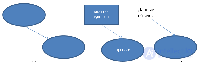
In case 1), if the upper process did not execute, the second cannot execute.
In 2), the process can execute, since the data of external entities is always available. The same applies to the attributes of the process itself
in 3) The result of the process can be data returning back
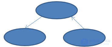
Conditional execution is possible – the process executes depending on conditions. In this case there is no data transfer, but there is a condition on execution – from the “conditional” process a dashed arrow is drawn indicating the condition of execution, for each transition.
Execution rules for the ADFD:
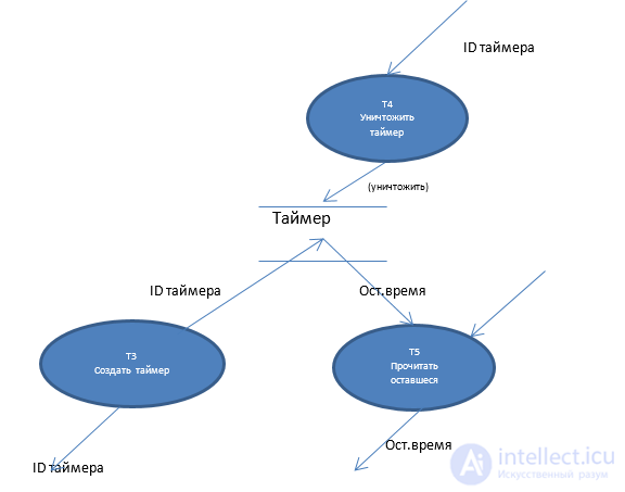
All processes can be split into four types.
Each process needs to be clearly named and described. Accessors – which attributes they read or write, which objects they create or destroy. Event generators – result event, event label. Transforms – what they do. Tests – “check that...”
All processes in a subsystem are combined into a single table. The same processes can occur in different actions – they will be shared. Shared processes can perform the same function, read and write and create and destroy the same objects, etc..

Based on the identified accessor processes, an object access model is built. On the access model, state models (of objects) are drawn as elongated ovals. If A uses the accessor of state model B, then an arrow is drawn, A will be an accessor.
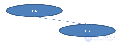
Accessors are implemented by adding attribute write and read actions to the object.
Entities can be clearly identified that appear, pass through distinct stages and cease to exist. Accordingly, the world can be represented through the change of state of objects.
Many things pass through distinct stages over the course of their existence.
The order of transition from one stage to another (evolution) forms a characteristic feature of the object's behavior
A real object is in a single stage of the behavior model at any moment of time
Things evolve from one stage to another abruptly
Not all evolutions between stages are permitted in a behavior scheme (an airplane on the ground must first take off and only then retract its landing gear)
In the real world there are incidents that force objects to transition from one stage to another – to evolve
The Moore state model is used to describe dynamic behavior. It consists of a set of states, a set of events (incidents), transition rules and state actions. For the transition rules either a StateTransitionDiagram or a StateTransitionTable is used. In the real world, the states of different entities (belonging to different classes) are coordinated with one another. A change in one state of one object leads to a change in the states of other objects. As a rule, we consider objects in relation to one another.
State – the position of an object in which a certain set of rules, lines of behavior, physical laws, etc. apply.
Three kinds of states can be distinguished:
Event – an abstraction of an incident or signal in the real world, which reports that something is transitioning to a new state.
Four aspects of events are distinguished:
There are a number of rules linking events and data.
Action – an operation that must be performed by an object when it reaches a certain state.
Only one action is associated with each state. When building a state transition diagram we try to describe the actions. Pseudocode is usually used for this. If the action is small, it can be placed directly under the state on the diagram; if large – then we take it out. What an action can do: any computation; generate an event for any object of any class; generate an event for something outside the scope of analysis; perform all work with a timer – create\delete\set\read. An action can have access to any attributes of any object, both its own and all others – read, write.
However, restrictions are placed on the execution of an action:
Events can be deferred until an action has been performed. Each event ceases when it “stops being” an event.
We approach the identification of the State Model as a formalization of asynchronous interaction – an incident occurs, and as a result objects change state. The change of state may occur not instantly, but some time after.
In which cases should life cycles (sets of states) be identified?
Concept
For each subsystem:
For each class:
For each state of each state model:
For each action (process):
We have identified the domain. It makes no sense to divide it into subsystems – we first need to populate it with entity-classes. The idea of information modeling: we begin by working with physical objects that exist in the real physical world; everything else will emerge as a result of their analysis. Physical objects are identified. We try to see what objects populate the domain, and split them into groups. We try to identify the characteristics of entities. If all objects have identical characteristics, they can be assigned to one class – a class is formed.
Attribute – each separate characteristic that is common to all possible instances of classes. Each attribute is defined by a set of values, which is important to determine during analysis in order to later determine the type of the attribute.
Identifier – that which clearly identifies a specific object. It can consist of one or several attributes. A change in an attribute does not lead to a change in the object itself – the object simply changes its “name”, but remains the same object.
Three types of attributes are distinguished:
Four rules for attributes are distinguished:
| <No.><name>(<key literal>) |
|---|
| * identifier_part |
| V Attribute |
| V Attribute |
Objects enter into interactions with one another, which needs to be formalized.
Relationship – an abstraction of a set of relations that systematically arises between different things in the real world – internal (R) and external (E).
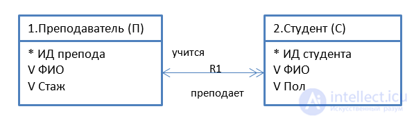
Next we need to identify the multiplicity of relationships. On each side there can participate one object, or one with many, or many with many: one-to-one, one-to-many, many-to-many – types of relationships. Training course – student, MtoM; Instructor – Student, OtoM.
Sometimes an object MAY not participate in a relationship on one side, in which case the relationship is – conditional (an instructor does not supervise students – a conditional relationship on the instructor's side, since a student must have a supervisor, but an instructor is not obliged to supervise). If objects on both sides MAY not participate in the relationship, then the relationship is – bi-conditional (Course – Student; the course is not taught this semester, or the student has not chosen this course). In total – 3 unconditional (OtoO, OtoM, MtoM), 4 conditional (OcToM, OToMc, McToM, MtoMc), 3 bi-conditional (OcTOc, OcToMc, McToMc).
When formalizing a relationship, an auxiliary attribute is added to one of the objects in the relationship. For an OtoM relationship the attribute is added on the many side – since an attribute cannot contain an internal structure. However, for an MtoM relationship a so-called associative class is added, which formalizes the relationship. An owner can own many apartments, an apartment can have many owners.

Ownership formalizes the relationship. Its address and full name clearly identify the two objects that are in relationship R1.
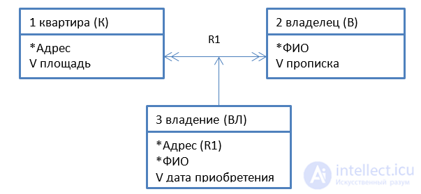
If the relationship is OtoO and one object is deleted, then the second object participating in the relationship must also be deleted or changed – if there is no wife, the husband becomes a widower or a bachelor. This will be a different object of a different class. If there is conditionality in the relationship (the relationship has dynamic behavior), then such a relationship must be formalized with an associative object. In this case conditionality is not required, dynamics alone is enough – there was one relationship, then it changed. Situations can arise where some relationships turn out to be the result of other relationships. Student – advisor – department. The advisor is chosen from the same department as the student.
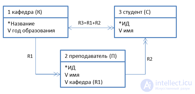
Wife – husband, associative object – marriage certificate, may have a relationship with the registry office where it was issued.
When there is a large system, we divide the task into domains.
Application domains – the main domains that directly solve the task.
Service domains – provide functions needed to support the application domain, all kinds of service functions.
Architectural – the domain responsible for the architecture of the system's construction (one domain per system); provides the general mechanisms for controlling the system.
Implementation domains – standard, library functions and so on. They make it possible to easily replace one implementation with another.
One domain uses the capabilities and mechanisms of another – there is a bridge between these domains. The one that provides the capabilities is called the server; the one using them – the client. The client views the bridge as a set of some offerings that someone presents to it. The server – a set of requirements. A domain-level diagram as a rule contains at the top – the domains most aware of the system (application domains), at the bottom – service and implementation domains.
When splitting up the task, different technologies can be used to design each domain. For example, in a rendering task, the actual drawing – a structural approach, while the various interactions on the scene – an object-oriented one. The domain approach makes it possible to later easily replace one domain with another; a server is viewed as a set of offerings.
An application domain is split into subsystems, while a service domain – is simply a set of functions. For a domain, just as for a subsystem, three diagrams are drawn.
Software development cycles using OO design:
Main stage: OO analysis, taking the most time. The task of OOA – building a system model. Design is carried out on the basis of the model that has been built.
Design – translation of the model into design documents using CASE tools.
Evolution. Writing code, testing, iterating — the OO approach thanks to recursive design, the system unfolds and grows more complex. Modification – evolving a finished product that has been delivered to the customer.
Advantages of recursive design during evolution:
Changes in the system, in order of worsening scenario:
The task of analysis – bring the model to a state where the interface will no longer need to be changed.
OO analysis
In structured programming the black box principle is used – we don't think about specific actions and data, but about what needs to be done. In OOP – the white box, data comes first of all. We identify the characteristics of objects, and only then arrive at how to process them.
The system is broken down into domains – interface, implementation, the task itself, service functions (for example communication) and so on. A domain diagram is drawn for the domain level of the whole task. To carry out the stages of analysis, a design matrix is drawn – we track which stages of analysis we have completed. A domain with more than 150 classes is hard to work with, and in practice – even with more than 50. Within a domain, groups of classes with many connections between them are clearly distinguished, while there are few connections between groups – the domain is split into subsystems, and we design the subsystems first, then implement the connections.
For the domain a subsystem connection model is built. Synchronous and asynchronous interaction schemes are distinguished, corresponding to the subsystem access model (synchronous) and the subsystem interaction model (asynchronous).

Comments