
Lecture
The measuring instrument market offers devices implementing a variety of level measurement methods, each with its own advantages and disadvantages. There is no universal solution for all cases, but several measurement methods may be workable in some processes. This section describes the most common level measurement methods, along with their advantages and disadvantages.
- continuous level measurement
1.1 Measuring principle
A guided-wave radar level gauge (GWR) is also called a time-domain reflectometer (TDR) or a micro-impulse radar (MIR).
A guided-wave radar level gauge is mounted on the roof of the tank or in a bypass chamber, with the probe length equal to the depth of the vessel/chamber.
A low-power microwave pulse travels down the probe at the speed of light. At the point of contact between the probe and the liquid (the air/liquid interface), a significant portion of the energy is reflected and returns back up the probe to the receiver.
The level gauge measures the time delay between the emission and reception of the emitted and reflected signals, after which the built-in microprocessor calculates the distance to the surface of the measured medium using the formula:
Distance = (Speed of light x time delay) / 2
If the distance to the reference point - usually the bottom of the tank or chamber - was specified when configuring the level gauge, the microprocessor calculates the liquid level.
Part of the microwave pulse continues to propagate through the liquid with a low dielectric constant, and the level gauge can register a second echo from the interface between liquids.
Thanks to this feature, guided-wave radar level gauges are successfully used to measure the level of a liquid/liquid interface, such as oil and water, as well as to measure liquid level through a layer of foam.
Guided-wave radar level gauges can be used in tanks with complex geometry, bypass chambers and vessels with tall nozzles. They are suitable for measuring the level of liquids with low dielectric constant values, under turbulent surface conditions. Since the operation of a guided-wave radar level gauge does not depend on how "flat" the surface is, it can be used to measure the level of powders and granular materials with a sloped surface, or liquids whose surface forms a vortex.
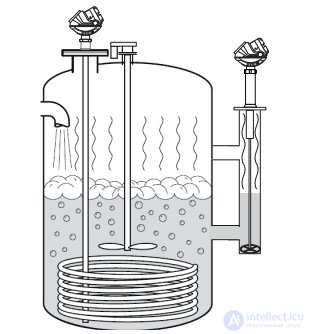
Fig. 1.1. A guided-wave radar level gauge can operate near objects that create interference, and under harsh process conditions
1.2 Advantages
Guided-wave radar level gauges are capable of simultaneously measuring level and the level of an interface between media, providing reliable measurements across a range of process applications. Guided-wave radar level gauges implement a "top-down" measurement method and provide a direct measurement of the distance to the surface of the medium. They can measure the level of liquids, slurry and bulk solids. A key advantage of such level gauges is that there is no need to adjust settings when the density, dielectric constant or electrical conductivity of the liquid changes. Changes in pressure, temperature and the state of the vapor space above the liquid have practically no effect on measurement error.
In addition, guided-wave radar level gauges have no moving parts, which minimizes the need for maintenance. A guided-wave radar level gauge is easy to install and can replace instruments based on other level measurement principles, such as capacitive and displacer level transmitters; installation is possible even with product already present in the tank.
1.3 Limitations
Although guided-wave radars can operate under a very wide range of conditions, special attention should be paid to probe selection. Several probe options are available, and the choice is made based on the process conditions, the required length and installation constraints. Probes must not come into contact with metal objects (except for coaxial probes), as this affects the measurement signal. If the measured medium tends to build up or form deposits, single-rod probes should be used. Some guided-wave radar level gauges are equipped with advanced diagnostic capabilities that can detect deposits on the probe. Chambers up to 75 mm in diameter are more susceptible to deposits, and it is harder to avoid contact between the probe and the chamber walls in them.
- continuous level measurement
2.1 Measuring principle
Non-contact radar level gauges implement two main methods of radio wave emission - pulse and frequency-modulated continuous wave (FMCW).
A pulse non-contact radar emits radio waves which, after reflecting off the surface of the measured medium, return back to the receiver. The level gauge measures the time delay between the emission and reception of the emitted and reflected signals, after which the built-in microprocessor calculates the distance to the surface of the measured medium using the formula:
Distance = (Speed of light x time delay) / 2
When configuring the level gauge, the distance to the reference point - usually the bottom of the tank or chamber - is specified, and the microprocessor calculates the liquid level.
A frequency-modulated radar level gauge also emits radio waves toward the surface of the product, but the frequency of the radio waves is continuously changing. When the radio emission reflects off the liquid surface and returns to the level gauge, it is compared with the radio emission currently being transmitted into the tank. The frequency difference between the transmitted and received radio signal is directly proportional to the distance to the liquid surface.
Since the measurements are taken without contact and the parts of the level gauge are practically not subject to corrosion, such level gauges are an ideal choice for measurements of viscous, sticky media and liquids with abrasive inclusions. Non-contact level gauges are quite often used in tanks with agitators. If necessary, a radar level gauge with a high operating frequency can be isolated from the process by a ball valve. Most manufacturers offer non-contact radars for measuring ranges from 1 to 30 or 40 meters.
The operating frequency of a non-contact radar level gauge affects its characteristics. A low frequency reduces the level gauge's susceptibility to vapors, foam and antenna contamination, while higher frequencies promote greater concentration of the radio emission, which minimizes the influence of nozzles, walls and internal tank structures. The beam angle is inversely proportional to the antenna size, which means that at the same operating frequency, the width of the measurement beam decreases as the antenna size increases.
2.2 Advantages
Non-contact radar level gauges implement a "top-down" measurement method and provide a direct measurement of the distance to the surface of the medium. They can measure the level of liquids, slurry and bulk solids. A key advantage of such level gauges is
that there is no need to adjust settings when the density, dielectric constant or electrical conductivity of the liquid changes. Changes in pressure, temperature and the state of the vapor space above the liquid have practically no effect on measurement error. In addition, non-contact radar level gauges have no moving parts, which minimizes the need for maintenance. If necessary, radar level gauges can be isolated from the process by polytetrafluoroethylene (PTFE) diaphragms, or by ball valves. Since the instrument does not come into contact with the measured medium, it can be successfully used for work with aggressive and contaminated media.
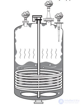
Fig. 2.1. Non-contact radars with antennas of various types for use under various conditions.
2.3 Limitations
A key condition for the successful operation of a non-contact radar is its correct installation on the tank. The surface of the measured medium must be clearly visible from the planned installation location, and the mounting nozzle must have smooth walls without protruding weld seams.
Internal tank structures: pipes, reinforcements, mixing devices can cause interference echoes, but most level gauges are equipped with sophisticated software algorithms that allow the level gauge to mask and ignore such interference.
A non-contact radar can be used under conditions of turbulence and mixing, but the success and quality of the measurements will depend on the dielectric constant of the liquid and the intensity of the surface disturbances. Foam can affect the measurement. Light, air-entrained foam generally does not reflect microwaves, while dense, heavy foam can reflect microwaves.
Liquids with a low dielectric constant absorb most of the emitted energy, and only a comparatively small portion of it is reflected back to the level gauge. Water and most aqueous solutions have a high dielectric constant, while petroleum products, oils and some bulk solids have a low dielectric constant.
If the surface of the medium is turbulent due to mixing, blending of products, or splashing on the surface, a significant portion of the microwave signal is scattered. Thus, the combination of a low dielectric constant and a turbulent surface can substantially limit the portion of the microwave signal that returns to the radar level gauge. This problem can be solved by installing a stilling well or a bypass chamber to provide a calm surface within the field of view of the level gauge.
- continuous level measurement
3.1 Measuring principle
An ultrasonic level gauge is mounted on the roof of the tank and sends ultrasonic pulses toward the measured medium. The ultrasonic pulse, which propagates through space at the speed of sound, reflects off the surface of the liquid. The level gauge measures the time delay between the moment of emission and the reception of the reflected pulse, and the built-in microprocessor calculates the distance to the liquid surface using the formula:
Distance = (Speed of sound x time delay) / 2
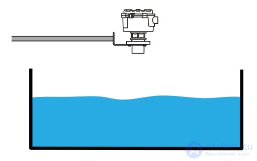
Fig. 3.1. Example of an ultrasonic level gauge installation
When configuring the level gauge, a reference height value is specified - usually the distance from the bottom of the tank to the level gauge - and the instrument calculates the level in the tank.
3.2 Advantages
Ultrasonic level gauges can be installed on either an empty or a full tank. As a rule, commissioning is very simple thanks to built-in configuration tools that allow start-up within a few minutes.
Thanks to the absence of moving parts and contact with the measured medium, ultrasonic level gauges require practically no maintenance. The wetted parts are typically made of inert fluorocarbon materials resistant to condensate from process media.
Since the level gauge is non-contact, the measurement results do not depend on changes in the density, dielectric properties or viscosity of the medium; ultrasonic level gauges are well suited for measuring the level of various aqueous solutions and chemicals. Changes in process temperature cause changes in the propagation speed of the ultrasonic pulse through the vapor space above the liquid; these deviations are generally corrected automatically based on readings from a built-in or remote temperature sensor. Changes in process pressure do not affect the measurement result.
3.3 Limitations
The operation of ultrasonic level gauges is based on the assumption that the ultrasonic pulse does not change its propagation speed. Applications where vapors or dense fumes form above the liquid surface should be avoided. In such cases, it is recommended to use radar level gauges.
Since the ultrasonic pulse propagates through air, ultrasonic level gauges cannot be used in processes with significant vacuum pressure.
The construction materials used limit the operating temperature to 70° C and the operating pressure to 3 bar.
The condition of the liquid surface is also of great importance. Some turbulence is acceptable, but foam often attenuates the reflected echo signal.
Internal tank structures, such as pipes, baffles, mixing devices, etc., cause false reflections, but most level gauges incorporate special software algorithms that allow these reflections to be tracked or ignored.
Ultrasonic level gauges can be used in silos containing bulk solids in the form of granules, grains or powders, but commissioning in such applications is difficult due to factors such as the angle of the surface slope, dust in the space and large measuring ranges. Guided-wave radar level gauges are better suited for work with bulk solids.
- continuous level measurement
4.1 Operating principle
Monitoring of solids content
The solids content in a suspension can be measured from the degree of attenuation of an ultrasonic signal passing through the suspension.
An ultrasonic transmitter/receiver pair is submerged in the tank, or may be installed in a pipe. The ultrasonic signal transmitted from the transmitter to the receiver is attenuated by the solid particles in the suspension. The power of the received signal is inversely proportional to the solids content in the suspension (the density of the suspension).
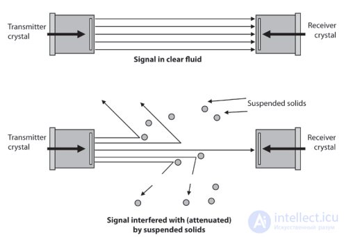
Fig 4.1 Principle of solid sediment content measurement
Sediment level measurement
An ultrasonic level gauge can be used to detect the presence of a sediment layer in a liquid and to measure its level in a clarifier or thickener.
The sensing element of the ultrasonic level gauge is submerged in the supernatant liquid, and ultrasonic pulses are directed vertically downward toward the sediment layer. The sediment layer reflects the pulses, which are picked up by the sensing element of the level gauge.
The measuring system measures the propagation time of the pulse from the level gauge to the sediment layer. If the reference height and the speed of sound in the liquid are set in the level gauge, the electronics unit calculates the sediment level.
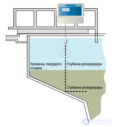
Fig. 4.2 Diagram of a settling tank
4.2 Advantages
Ultrasonic level gauges are easy to install, often have built-in configuration tools, and can thus be quickly commissioned.
Since the sensing element of the level gauge is submersible, the measurement does not depend on the condition of the surface, or the presence of vapors and foam on the surface.
The measuring principle does not depend on the optical properties of the liquid, and provides freedom from moving parts, so such measuring systems require practically no maintenance.
4.3 Limitations
Submersible ultrasonic level gauges are designed for use in liquids where the suspended solids content is within the range of 0.5 .. 15%. If the supernatant liquid contains a higher amount of suspended solids, the measuring ultrasonic signal may be completely scattered.
The ultrasonic signal can also be attenuated by air/gas bubbles in the supernatant liquid. Gas/air bubbles can increase the measurement error.
An additional limitation is that continuous submersion of the sensing element must be ensured.
- continuous level measurement
5.1 Measuring principle
Pressure sensors are the most widely used liquid level measurement technology. They have a simple design, are easy to install and operate, and work in the widest variety of applications and across a broad range of process conditions.
If the level is measured in an open/vented tank, a single gauge pressure (hydrostatic pressure) sensor (GP) or a differential pressure (DP) sensor can be used. If the tank is closed or pressurized, differential pressure must be measured to compensate for the pressure in the tank.
In addition to basic level measurement, differential pressure sensors can be configured to measure density or the level of an interface between media.
Level measurement in an open tank
To obtain the level value in an open tank, the hydrostatic pressure of the liquid must be measured. A column of liquid exerts a force on the base of the column, due to the weight of the liquid. This force, called hydrostatic pressure or the pressure of the liquid column, can be measured in units of pressure. Hydrostatic pressure is determined by the following equation:
Hydrostatic pressure = Height x Specific weight
As the level (column height) of the liquid changes, the hydrostatic pressure changes proportionally. Therefore, the simplest way to measure the level in a tank is to install a pressure sensor at the lowest level. The liquid level above the measurement point can be obtained from the hydrostatic pressure value by transforming the formula above to calculate height. If the units of pressure measurement do not correspond to the units of length measurement, a unit conversion must be performed (1 m of water column = 0.1 kg/cm2).
Level measurement in a closed tank
If the tank is pressurized, the reading of a single gauge pressure sensor is not sufficient, since the sensor cannot distinguish whether a change in the total pressure is caused by a change in liquid level or by a change in pressure within the tank. To solve this problem, a differential pressure sensor must be used in closed tanks to compensate for the pressure in the tank.
When measuring differential pressure, a change in the total pressure in the tank acts equally on the upper and lower taps, so the influence of the internal pressure is completely eliminated.
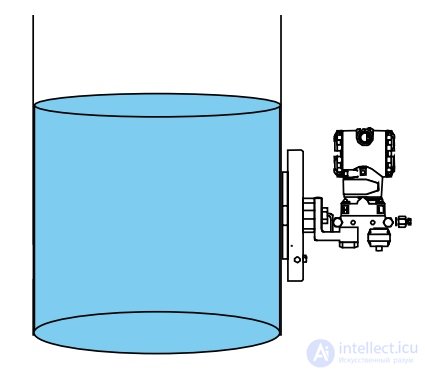
Fig. 5.1. Differential pressure sensor (DP)
At the lower tap, near the bottom of the tank, the sum of the hydrostatic pressure and the pressure in the vapor space is measured. At the upper tap, only the pressure in the vapor space is measured. The pressure difference between the taps (differential pressure) is used to determine the level.
Level = Differential pressure / Specific weight
5.2 Advantages
Overall, pressure sensors are an economical, easy-to-operate and well-understood solution. In addition, pressure sensors can be used in practically any tank and with any liquids, including suspensions, and can operate across a wide range of pressures and temperatures, as well as in the presence of foam and a turbulent surface.
5.3 Limitations
The level measurement error of pressure sensors can be affected by changes in liquid density. Special precautions must be taken when working with viscous, corrosive or otherwise aggressive liquids. In addition, some media (such as cellulose pulp) tend to solidify as concentration increases. Pressure sensors do not work with media in a solid state. If pressure sensors are installed with impulse lines (dry and wet legs), their operation will be affected by changes in ambient temperature due to changes in the density of the fill fluid in the wet leg or the accumulation of condensate in the dry leg. Sealed capillary systems mitigate the effect of some of these factors and can be chosen to reduce additional error.
Measuring systems with remote electronic diaphragm seals can further reduce the error associated with temperature change, since the impulse lines in them are replaced by digital communication lines. However, systems with remote electronic diaphragm seals are designed for use on tall tanks with low and medium static pressure values.
- continuous measurement and discrete level control
6.1 Measuring principle
When an electrode is installed for level measurement in a tank, a capacitor is formed. The metal rod of the electrode acts as one of the capacitor plates, and the tank wall (or a reference electrode in non-metallic tanks) acts as the other plate. As the level rises, the air or gas surrounding the electrode is displaced by the material, which has a different dielectric constant. The change in capacitance of the capacitor occurs because of the change in the dielectric properties of the medium between the plates. This change is registered by electronic circuits for measuring capacitance and converted into a command for an actuating relay or into a proportional output signal.
The dependence of the capacitor's capacitance is expressed by the following equation:
C = K ( A / D )
where:
C = capacitance in farads;
K = dielectric constant of the material; A = area of the plates in square meters;
D = distance between the plates in meters;
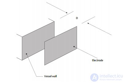
Fig. 6.1. Operating principle of a capacitive level gauge
The dielectric constant is a numerical value on a scale from 1 to 100, which characterizes the ability of the dielectric (the medium between the plates) to hold an electrostatic charge. The dielectric constant of a material is determined on a test bench. In real conditions the change in capacitance occurs in different ways, depending on the properties of the measured medium and the choice of the level-measuring electrode. However, the basic principle always remains valid. If a medium with a low dielectric constant is displaced by a medium with a high dielectric constant, the total capacitance of the system increases.
As the size of the electrode increases (increasing the effective surface area), the capacitance increases; as the distance between the measuring and reference electrodes increases, the capacitance decreases.
6.2 Advantages
A capacitive level gauge can be used across a wide range of process parameters, in particular under variable density, elevated temperatures (up to 540 °C), high pressures (up to 345 bar), and in the presence of viscous/sticky products, foam and pastes. It can be used for continuous or point-level measurement of liquids and bulk solids, and is suitable for interface-level measurement. In addition, capacitive level gauges are distinguished by their low cost.
6.3 Limitations
Changes in the dielectric properties of the medium, as well as product build-up on the probe, lead to measurement errors of the capacitive level gauge. Various options exist for compensating for the effect of product build-up on capacitive probes. In non-metallic tanks, or in tanks without vertical walls, an additional reference electrode is required. Calibration of a capacitive level gauge can be difficult, especially where "bench calibration" is not possible, and changes in the characteristics of the vapor space can affect the output signal. In addition, the operation of capacitive level gauges is severely hindered under conditions of heavy foaming.
- continuous level measurement
7.1 Measuring principle
A displacer level gauge is mounted on the roof of the tank or, more often, in an external chamber connected to the tank through nozzles with shutoff valves. Structurally, the level gauge consists of a displacer mounted on a suspension, connected to a torsion tube or suspended on a spring-loaded suspension, which is connected to the electronic transmitter of the level gauge or switch. The displacer is designed to be heavier than the liquid in which it will operate, so that even when the displacer is fully submerged in the liquid, gravity continues to act on the suspension.
As the liquid level in the tank rises, the displacer is submerged deeper into the medium. A buoyant force acts on the displacer, proportional to the weight of the liquid displaced by the displacer (Archimedes' law). The decrease in the apparent weight of the displacer is sensed by the electronic transmitter of the level gauge, and since the weight of the displacer is proportional to the liquid level, the level gauge's electronics unit can calculate the liquid level.
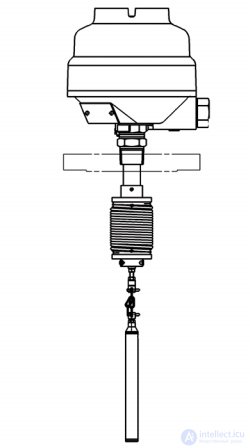
Fig. 7.1. General view of a displacer level gauge
7.2 Advantages
The installed base of displacer level gauges and switches is enormous, and provided that maintenance and calibration are performed regularly, they operate reliably for many years. These instruments are widely used owing to their ability to operate at high process pressures and temperatures, as well as their ability to measure interface level even in the presence of emulsion layers between the liquids, which allows level measurement under severe operating conditions.
7.3 Limitations
The level measurement error depends on how correctly the instrument is calibrated for the operating conditions. If the operating parameters change, the level measurement will be made with an increased error.
Displacer level gauges with a torque-tube suspension are particularly demanding in terms of periodic maintenance and correct calibration. In addition, such level gauges can be damaged under conditions of sharp level fluctuations.
The use of displacer level gauges over measuring ranges of more than 5 m is considered impractical, mainly due to the complexity of installation
- continuous measurement and discrete level control
8.1 Measuring principle
Radioisotope level gauges consist of a shielded radioisotope source, placed on one side of the tank or pipe, and a receiver, placed on the opposite side. Gamma rays are emitted by the source and directed through the wall
of the tank, through the medium contained in it, toward the opposite wall of the tank, where the receiver is located. Radioisotope level switches use sources of a specific size that provide a radiation level detectable when there is no material between the source and the receiver.
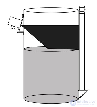
Fig. 8.1. General view of a radioisotope level gauge
Radioisotope level gauges use similar sources, but they determine the amount of attenuation of the gamma radiation passing from the source to the detector through the thickness of the measured product. The dose registered by the receiver is inversely proportional to the amount of product in the tank.
Although the word "radioisotope" sometimes raises concern, there is well-documented experience of the safe use of this method for more than 30 years.
8.2 Advantages
The greatest advantage of the radioisotope measurement method is that it requires absolutely no contact with the process, meaning no process connections are needed to install the instrument on the tank. In addition, radioisotope level gauges are non-contact and are not affected by high temperatures, pressures, or aggressive, abrasive and viscous materials, and are insensitive to agitation, fouling or silting. They can be used for continuous level measurement or level alarm of liquids, bulk solids, as well as for determining interface level.
8.3 Limitations
Significant density fluctuations, especially changes in hydrogen concentration in the product, can cause measurement errors. Material build-up on the tank walls can also affect measurement results. Use of the radioisotope method requires a use permit and mandatory monitoring for the absence of radiation leaks, as well as compliance with strict occupational health and safety requirements when handling and disposing of the radiation sources. In addition, radioisotope level gauges have a rather high cost.
- continuous level measurement
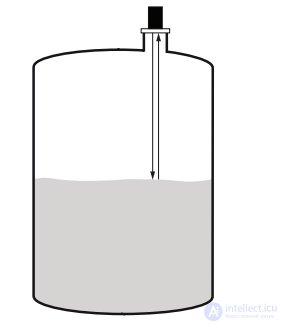
Fig. 9.1 Laser level gauge
9.1 Measuring principle
A laser level gauge uses a source of focused infrared radiation, which is directed toward the surface of the medium. The laser radiation is reflected from most liquid and bulk media. To measure the distance from the level gauge to the surface, the propagation time of the infrared radiation is measured with high accuracy.
9.2 Advantages
The narrow, focused laser beam makes these level gauges suitable for use in tanks with limited internal space.
This is a non-contact level gauge, with no moving parts, requiring only a small amount of maintenance. Laser level gauges work well in opaque, highly reflective liquids or bulk media. Laser level gauges can track rapid level changes and can provide level measurement over large ranges.
9.3 Limitations
For normal operation of a laser level gauge, the protective glass of the laser emitter must remain clean. Therefore, level gauges of this type cannot operate under dusty conditions or in the presence of fog.
In addition, the laser beam may fail to reflect from the surface of calm, transparent liquids. During installation, it is critically important to maintain perpendicularity of the level gauge's axis to the surface of the liquid.
- continuous level measurement
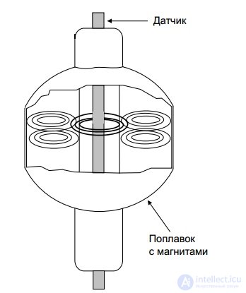
Fig. 10.1. Occurrence of magnetostriction from the interaction of magnetic fields
10.1 Measuring principle
Magnetostrictive level gauges determine the moment of intersection of two magnetic fields, one of which is created by the magnet of the float, and the other by the waveguide. The electronics generate a low-power current pulse that propagates along the waveguide, and when the magnetic field of the pulse interacts with the field created by the float's magnet, a "twist" occurs in the sensing element. This generates an ultrasonic wave, whose propagation time is measured by the electronics of the level gauge.
10.2 Advantages
Magnetostrictive level gauges are distinguished by low measurement error (±1 mm). A single level gauge can measure both the level and the interface level, and can also measure the process temperature at one or several points.
10.3 Limitations
A magnetostrictive level gauge measures the position of the float, so a change in the density of the measured medium will cause an increased measurement error. Since the floats are in contact with the measured medium, they can lose mobility and are subject to corrosion. Level gauges for large measuring ranges (more than 3 m) can be put out of operation by a turbulent surface or due to installation errors. In addition, the float's magnet attracts all metallic particles contained in the liquid, which changes the properties of the float.
- continuous level measurement
11.1 Measuring principle
A magnetic level indicator is a vertical indicator consisting of a chamber mounted on the process tank, and a column with visual indicators for displaying the level.
Magnetic floats are placed in the chamber, which move up and down together with the surface of the medium and switch or move the indicators in the column. The floats can also control the switching of magnetostrictive sensors sensitive to the magnetic field.
The indicator chamber is made of a non-magnetic material, resistant to the process media and capable of withstanding the effects of temperature and pressure. The chamber is mounted on the process tank in such a way that the liquid level in the chamber matches the liquid level in the tank, but the surface of the medium in the chamber is calmer. The chamber is connected to the tank through nozzle pipes and may have several connections. It contains the same liquids and interfaces as the process tank, provided that the connections ensure proper communication between the chamber and the tank.
The magnetic float or floats located in the chamber are designed so as to remain at the level of the upper liquid and/or at the interface between two liquids, taking into account their specific gravity. The indicators usually consist of a housing in which a column with flags or rollers is placed. Lines of force from the magnetized float pass through the walls of the chamber and act on the flags or rollers, causing them to flip to their reverse side, painted in a contrasting color.
In this way, the position of the float (floats) in the chamber is indicated. As the liquid level or the interface level in the chamber rises and falls, the float (floats) rises and falls accordingly, and the level position is displayed on the indicator. The lines of the magnetic force field can also act on magnetostrictive sensors or magnetic relays of any type, for example, reed switches, mounted on the column.
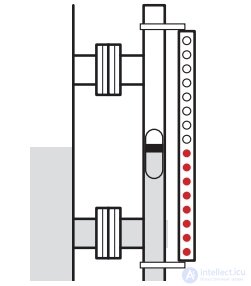
Fig. 11.1 Magnetic level indicator
11.2 Advantages
Magnetic level indicators are typically used as a means of visual indication of liquid level in a tank and are intended for process personnel. Their advantage over an ordinary sight glass is that the indicator itself contains no process liquid, which eliminates the danger of liquid release into the environment in the event of glass failure or a leaking seal. In addition, level observation from a distance is possible, monitoring of colorless liquids is possible, and the level is clearly visible even for liquids that cause fouling or etching of the sight glass. Magnetic indicators are typically in service for decades.
11.3 Limitations
Magnetic level indicators use floats, which are prone to fouling and sticking. If iron filings are present in the medium, they can be captured by the magnets and cause the float to jam. In addition, a sticky medium containing paraffin-like substances can cause the float to jam or hang up if the temperature of the chamber drops below the temperature of the process. Floats can be damaged during hydraulic testing, steam cleaning, and during process start-up and shutdown.
In magnetic level indicators, a companion float is sometimes used, which is magnetically coupled to the main float and moves together with it. There are known cases where the coupling between the main float and the indicator float is lost, in which case it becomes necessary to reset the indicator to its initial state. The design of "flag"-type indicators is comparatively resistant to such phenomena. Under certain circumstances, boiler-inspection regulations require direct monitoring of the process medium level. In such cases, magnetic indicators are not used.
The design of the float depends on the pressure in the tank and the specific gravity of the process liquid across the entire range of operating temperatures. The most demanding processes are those combining high temperature, high pressure and low specific gravity; magnetic indicators can be used at temperatures up to 538 °C, at pressures above 275 bar, and in liquids with a specific gravity of 0.4 or lower.
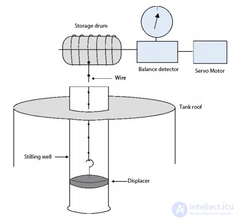
Fig. 1.1 Diagram of a servo level gauge
12.1 Operating principle
A level gauge equipped with a servo drive uses a reversible motor, to which a wire and a displacer are attached. The wire, to which the displacer is attached, is wound on a measuring drum. The servo motor is controlled by electronic scales, which continuously monitor the buoyancy of the partially submerged displacer. In a state of equilibrium, the weight of the partially submerged displacer is balanced by the force of counterbalancing springs.
A rise or fall in the level causes a change in the buoyant force. A balance detector acts on an integrating circuit in the motor, which, in turn, rotates the measuring drum, and the displacer rises or falls until the equilibrium position is restored.
Servo level gauges are usually mounted on the roof of the tank in a stilling well. The well is necessary to ensure minimal measurement error and to eliminate horizontal displacement of the displacer.
If the displacer is not located in the stilling well, its operation can be affected by installation errors.
Servo level gauges can also be used for interface-level measurement. In this case, the displacer will be designed to float in the denser medium and sink in the upper layer of the medium.
Factors affecting the error of the system include: elongation of the wire due to temperature changes, the installation location, deformation of the tank under the action of the liquid, which causes displacement of the reference point, fluctuations in product density, as well as manufacturing tolerances of the wire and the drum.
12.2 Advantages
A level gauge equipped with a servo drive uses a reversible motor, to which a wire and a displacer are attached. The wire, to which the displacer is attached, is wound on a measuring drum. The servo motor is controlled by electronic scales, which continuously monitor the buoyancy of the partially submerged displacer. In a state of equilibrium, the weight of the partially submerged displacer is balanced by the force of counterbalancing springs. A rise or fall in the level causes a change in the buoyant force. A balance detector acts on an integrating circuit in the motor, which, in turn, rotates the measuring drum, and the displacer rises or falls until the equilibrium position is restored.
A servo level gauge provides direct level measurement with low absolute error (±0.5 mm). Some servo level gauges allow remote activation of the raising and lowering of the measuring displacer for the purpose of checking reproducibility and technical characteristics, or for calibration. Lowering the displacer also makes it possible to measure density and/or detect the water layer boundary at the bottom of the tank beneath the surface of the product.
To ensure minimal measurement error, the displacer must be installed in a stilling well to limit its horizontal movement.
A servo level gauge has many moving parts, which are subject to mechanical wear and are also sensitive to fouling and build-up.
A change in the density of the measured product can affect the settling of the sensing element in the equilibrium state.
Although a servo level gauge can also be used to measure density and/or detect a water interface, this is achieved by immersing the wire and displacer, which can leave product deposits on them. This can lead to an increased volume of maintenance in order to keep measurement error at a minimum. Product level measurement is not possible while density and water interface position are being measured.
Servo level gauges are usually mounted on the tank roof, in a stilling well. The stilling well is needed to keep measurement error at a minimum and to eliminate horizontal displacement of the displacer.
If the displacer is not located in a stilling well, mounting errors can affect its operation.
Servo level gauges can also be used to measure the interface between media. In this case the displacer is designed to float in the denser medium and sink in the layer of the upper medium.
Factors affecting the error of the system include: wire elongation due to temperature changes, the installation location, tank deformation under the weight of the liquid, which causes displacement of the reference point, product density fluctuations, and manufacturing tolerances of the wire and drum.
- discrete level monitoring
13.1 Operating principle
A vibrating level switch consists of a fork with two tines that vibrates at its natural frequency under the action of a piezoelectric element. The switch is mounted on top of or on the side of the tank, on a flanged or threaded process connection, so that the fork is located inside the tank.
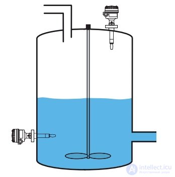
Fig. 13.1. Examples of mounting vibrating-fork level switches on a tank
In air, the fork vibrates at its own resonant frequency, which is continuously monitored by the electronics. The moment the fork is immersed in liquid, the vibration frequency changes. The change in frequency is detected by the switch's electronics, which in turn changes the switch's output state to alert the operator, or to control a pump or valve. The switch's operating frequency is chosen so as to avoid the effect of vibration that may be present during operation of the process plant, and to avoid possible false trips.
The switch's design contains no external seals and is usually made of stainless steel, which allows it to be used at high pressures and temperatures. Versions with coated wetted parts or made of special materials for use in aggressive media are also available.
13.2 Advantages
The operation of vibrating level switches is practically unaffected by: liquid flow, turbulence, bubbles, foam, vibration, solid inclusions, build-up, deposits, and changes in the properties/characteristics of the liquid. No additional calibration is required after installation on site. The switches have minimal mounting requirements, and the absence of moving parts and clearances practically eliminates the need for maintenance.
13.3 Limitations
Vibrating-fork level switches are unsuitable for use in very viscous media. Deposits between the tines of the fork lead to false trips.
- discrete level monitoring
14.1 Operating principle
A float-type level switch is usually mounted on the side wall of the tank or in an external chamber, and trips when the float rises under the action of the liquid reaching the set switch point. A permanent magnet is structurally linked to the float and interacts with a second permanent magnet inside the switch housing. The design contains no seals, since the magnets interact through the wall of the switch housing.
These simple electromechanical instruments are practically fail-safe and provide reliable tripping for high- or low-level control. Such switches are available in a wide range of designs, and a model can be selected to suit practically any process connection, any process, and any application.
In cases where the levels to be monitored are significantly below the switch's mounting point, a displacer-type switch can be used, whose operating principle is similar to that of a displacer level transmitter. A spring-loaded displacer on a cable is positioned at the required level.
The displacer applies a load of a certain magnitude to the suspension and spring. When the displacer is immersed in the liquid, the force acting on the spring decreases, and the working permanent magnet rises, interacting with the second permanent magnet in the switch housing. Displacer-type switches are often used in processes with very high pressures and with liquids of low density.
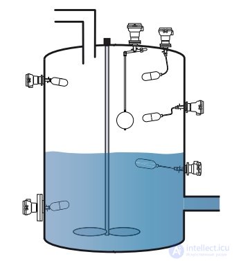
Fig. 14.1. Examples of mounting float-type switches
14.2 Advantages
Thanks to their simple design with few components, float-type and displacer switches are very reliable and easy to maintain. They withstand process conditions with high pressures and temperatures, and the variety of wetted-part materials available allows the switches to be used in practically any liquid.
14.3 Limitations
Float-type and displacer switches are simple passive devices with no self-diagnostic functions, so regular condition checks and maintenance are recommended. The moving parts of such switches are prone to fouling by sticky or viscous liquids.
- Continuous measurement and discrete level monitoring
15.1 Measurement principle
By measuring the resistance of the medium in an external chamber or pipeline, it is possible to detect water (its resistance is typically 2 Ω to 100 kΩ) and steam (its resistance is typically greater than 10 MΩ).
To measure the water level in a boiler drum, a set of electrodes can be installed, mounted in an external chamber connected to the drum. The electrodes are positioned above and below the normal water level in the drum. The resistance of the medium is measured at each electrode, and a stepwise change in the resistance of two adjacent electrodes is interpreted as the steam/water interface level.
The difference in resistance between water and steam can be used in systems that prevent water from entering turbine units. By measuring the resistance of the medium at electrodes installed in steam lines, it is possible to set up an alarm for the presence of water and take the appropriate safety measures.
15.2 Advantages
The conductive (conductivity-type) method of detecting steam and water is a proven measurement method. The difference between the resistance of water and steam is very large, which ensures simple and reliable measurement.
The use of an electronic method for measuring water level and detecting water/steam provides a high level of self-diagnostics and measurement reliability compared with mechanical level gauges, owing to the absence of moving parts. This significantly reduces the need for maintenance.
15.3 Limitations
Measurement reliability depends on water quality. It is usually very pure, but in contaminated water the electrodes can produce false trips. Nevertheless, advanced models of such level gauges make it possible to avoid false trips even in such cases.
The operating temperature limit is restricted by the materials used and is 500 °C.
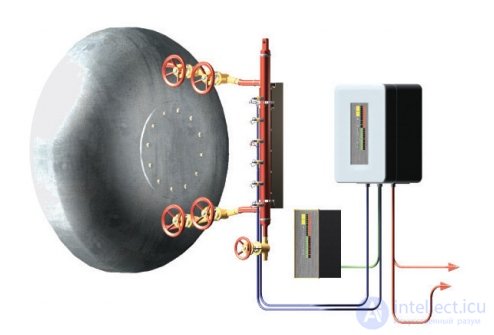
Fig. 15.1 Conductive (conductivity-type) level gauge on a boiler drum
|
Process conditions |
Differential pressure |
Capacitive |
Ultrasonic |
Guided-wave radar |
Non-contact radar |
Nuclear |
Laser |
Displacer |
Magnetostrictive |
Magnetic level indicators |
Servo level gauge |
|
Aeration |
2 |
1 |
2 |
1 |
2 |
2 |
2 |
1 |
2 |
1 |
2 |
|
Agitation |
1 |
2 |
3 |
3 |
1 |
1 |
2 |
1 |
2 |
1 |
2 |
|
Ambient temperature changes |
2 |
1 |
2 |
1 |
1 |
1 |
1 |
2 |
1 |
1 |
1 |
|
Corrosion |
2 |
1 |
1 |
2 |
1 |
1 |
1 |
2 |
2 |
2 |
2 |
|
Density changes |
2 |
1 |
1 |
1 |
1 |
2 |
1 |
2 |
2 |
2 |
3 |
|
Dielectric constant changes |
1 |
3 |
1 |
— |
1 |
1 |
1 |
1 |
1 |
1 |
1 |
|
Dust |
1 |
1 |
3 |
1 |
2 |
1 |
3 |
3 |
1 |
3 |
3 |
|
Emulsion |
1 |
1 |
1 |
2** |
1 |
1 |
1 |
1 |
2** |
2** |
2** |
|
Foam |
1 |
2 |
3 |
1 |
2 |
1 |
3 |
1 |
1 |
1 |
2 |
|
High process temperature |
1 |
1 |
3 |
1 |
2 |
1 |
1 |
1 |
3 |
1 |
2 |
|
High vessel pressure |
1 |
1 |
3 |
1 |
2 |
1 |
1 |
1 |
3 |
2 |
2 |
|
Internal obstructions in the vessel |
1 |
2 |
2 |
2 |
2 |
2 |
2 |
1 |
1 |
1 |
1 |
|
Low process temperature (-40°C) |
1 |
1 |
1 |
1 |
1 |
1 |
1 |
2 |
1 |
2 |
1 |
|
Vacuum vessel pressure |
2 |
1 |
3 |
1 |
1 |
1 |
1 |
1 |
1 |
1 |
1 |
|
RFI/motor noise |
1 |
1 |
2 |
1 |
1 |
1 |
2 |
1 |
1 |
1 |
1 |
|
Deposits/build-up |
3 |
3 |
2 |
2 |
1 |
2 |
2 |
3 |
3 |
3 |
3 |
|
Slurries |
2 |
1 |
1 |
2 |
1 |
1 |
1 |
3 |
2 |
2 |
3 |
|
Bulk solids |
3 |
2 |
2 |
1 |
1 |
1 |
1 |
3 |
3 |
3 |
3 |
|
Vapors |
1 |
2 |
2 |
1 |
1 |
1 |
2 |
1 |
1 |
1 |
1 |
|
Viscous, sticky media |
2 |
2 |
1 |
2 |
1 |
1 |
1 |
3 |
3 |
3 |
3 |
1 = Good: this condition has little or no effect on the performance of this method.
2 = Fair: this method may work under these conditions, but measurement reliability may be reduced or special installation may be required.
3 = Poor: this method is not suitable for these conditions.
* Changes in the dielectric constant affect the accuracy of interface level measurement.
** Total level: good; interface level: fair.
|
Process conditions |
Capacitive |
Nuclear |
Float-type |
Vibrating fork |
|
Aeration |
1 |
2 |
1 |
1 |
|
Agitation |
2 |
1 |
1 |
1 |
|
Ambient temperature changes |
1 |
1 |
1 |
1 |
|
Corrosion |
1 |
1 |
2 |
2 |
|
Density changes |
1 |
2 |
2 |
1 |
|
Dielectric constant changes* |
3 |
1 |
1 |
1 |
|
Dust |
1 |
1 |
1 |
1 |
|
Emulsion |
1 |
1 |
1 |
1 |
|
Foam |
2 |
1 |
1 |
2 |
|
High process temperature |
1 |
1 |
1 |
1 |
|
High vessel pressure |
1 |
1 |
1 |
1 |
|
Internal obstructions in the vessel |
2 |
2 |
1 |
1 |
|
Low process temperature |
1 |
1 |
1 |
1 |
|
Vacuum vessel pressure |
1 |
1 |
1 |
1 |
|
RFI/motor noise |
1 |
1 |
2 |
2 |
|
Deposits, product build-up |
3 |
2 |
2 |
2 |
|
Slurries |
1 |
1 |
2 |
2 |
|
Bulk solids |
2 |
1 |
3 |
3 |
|
Vapors |
2 |
2 |
1 |
1 |
|
Viscous, sticky media |
2 |
1 |
2 |
2 |
1 = Good: this condition has little or no effect on the performance of this method.
2 = Fair: this method may work under these conditions, but measurement reliability may be reduced or special installation may be required.
3 = Poor: this method is not suitable for these conditions.
Other articles:

Comments