
Lecture
A frequency meter — a radio measuring instrument for determining the frequency of a periodic process or the frequencies of the harmonic components of a signal's spectrum.
Their operation is based on the method of discrete counting.
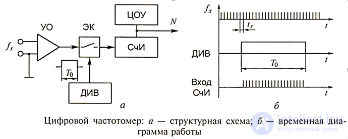
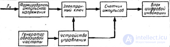
The block diagram of the frequency counter is shown in Figure 130. Its main components are: a pulse shaper for the input signal at the measured frequency fx, a reference-frequency generator, an electronic gate, a pulse counter with a digital display unit, and a control unit that organizes the operation of the instrument. Its principle of operation is based on measuring the number of pulses arriving at the counter input during a strictly defined time interval, equal in this instrument to 1 s. This required measurement time interval (gate time) is formed in the control unit.
The signal fx, whose frequency is to be measured, is applied to the input of the pulse shaper. There it is converted into rectangular pulses whose repetition rate corresponds to the frequency of the input signal. The converted signal is then fed to one of the inputs of the electronic gate, while the second input of the gate receives the gate-time signal that holds it open for a duration of 1 s.
As a result, a burst of pulses appears at the output of the electronic gate and, consequently, at the input of the counter. The logical state that the counter is left in after the gate closes is displayed by the digital display unit for the interval of time set by the control unit.
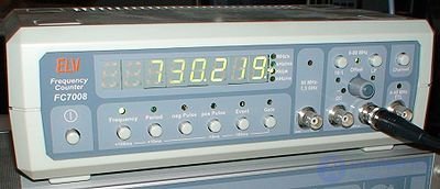
The operating principle of electronic-counting frequency counters is based on counting the number of pulses formed by the input circuits from a periodic signal of arbitrary shape over a given time interval. The measurement time interval is likewise set by counting pulses taken from the frequency counter's internal crystal oscillator or from an external source (for example, a frequency standard). Thus the frequency counter is a comparison-type instrument whose measurement accuracy depends on the accuracy of the reference frequency.
The electronic-counting frequency counter is the most widespread type of frequency meter owing to its versatility, wide frequency range (from a fraction of a hertz to tens of megahertz) and high accuracy. To extend the range to hundreds of megahertz — tens of gigahertz, additional units are used — frequency dividers and frequency transfer devices.
In addition to frequency, most electronic-counting frequency counters can measure the pulse repetition period, the time intervals between pulses, and the ratio of two frequencies, and can also be used as pulse counters.
Some electronic-counting frequency counters (for example, the Ch3-64) combine the electronic-counting and heterodyne measurement methods. This not only extends the measurement range but also makes it possible to determine the carrier frequency of pulse-modulated signals, which is not achievable by the simple counting method alone.
PURPOSE: servicing, adjustment and diagnostics of radio-electronic equipment for various purposes, monitoring the operation of radio systems and technological processes
Advantages
EXAMPLES: Ch3-33, Ch3-54, Ch3-57, Ch3-63, Ch3-64, Ch3-67, Ch3-84
The operating principle of resonance frequency meters is based on comparing the frequency of the input signal with the natural resonant frequency of a tunable resonator. The resonator may be a resonant (tank) circuit, a section of waveguide (cavity resonator), or a quarter-wave section of line. The signal under test passes through the input circuits to the resonator, and from the resonator the signal passes through a detector to an indicating device (galvanometer). To increase sensitivity, some frequency meters employ amplifiers. The operator tunes the resonator for the maximum indicator reading and reads off the frequency from the tuning dial.

The distinguishing features of resonance frequency meters used for measuring high and very high frequencies are their simplicity of design, rapid operation, and unambiguous measurement results; the measurement error is 0.1-3%.
A resonance frequency meter is an oscillatory system that is tuned into resonance with the measured frequency fx of the oscillations exciting it, which are supplied from the source under test through a coupling element. The resonant frequency is determined from the reading of a calibrated tuning control. The state of resonance is registered by means of a built-in or external indicator.
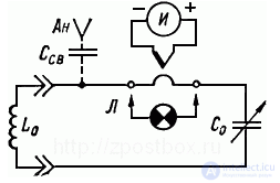
Frequency meters that measure frequencies from 50 kHz to 100-200 MHz are built as a resonant circuit made of lumped-constant elements: an inductor L0 and a variable capacitor C0 (Fig. 16). An EMF at the measured frequency fx is induced in the frequency meter's circuit, for example through inductive coupling with the source of oscillations via the coil L0 or a small whip antenna connected to socket An. With a low-power source, coupling to it may instead be capacitive, through a coupling capacitor Csv (with a capacitance of a few picofarads) and a coupling lead. By varying the capacitance of capacitor C0, the circuit is tuned into resonance with the frequency fx according to the maximum reading of the resonance indicator. In this case the measured frequency fx, equal to the circuit's natural frequency, is:
f0 = 1/(2π*(L0C0)0.5),
is determined from the scale of capacitor C0.
With a fixed inductance L0, the range of measured frequencies is limited by the coverage ratio, understood as the ratio of the frequency meter's maximum tuning frequency fmax to its lowest frequency fmin as the circuit capacitance varies from an initial value Cinitial to a maximum Cmax. The initial circuit capacitance Cinitial is made up of the initial capacitance of capacitor C0, the wiring capacitance, and the capacitances of the fixed or trimmer capacitors included in the circuit to obtain the required coverage ratio or for other purposes (Fig. 17). When it is necessary to extend the range of measured frequencies, the frequency meter is fitted with several coils of different inductance, either interchangeable (Fig. 16) or switchable (Fig. 17). In the latter case, unused coils (if not shielded) should preferably be short-circuited to prevent them from drawing energy out of the frequency meter's circuit at tuning frequencies close to their own natural frequencies; in that case, coupling to the source of oscillations is provided through the coupling socket An, or by means of an external coupling coil Lsv of one or more turns, connected to the circuit by a flexible high-frequency cable (Fig. 17).
Resonance indicators make it possible to register the state of resonance from the maximum current in the circuit or the maximum voltage across the circuit elements. Current indicators should have low resistance, and voltage indicators should have high resistance; the losses they introduce into the circuit will then not cause a noticeable blunting of the circuit's resonance curve.
Thermoelectric milliammeters with a full-scale deflection current of up to 10 mA, connected in series in the frequency meter's circuit, are sometimes used as current indicators (Fig. 16); when operating such a frequency meter, coupling to the object under measurement should be established very carefully, and the thermal instrument must not be allowed to be overloaded as resonance is approached. The simplest current indicator can be a miniature incandescent lamp L; the measurement error naturally increases in this case.
In modern frequency meters, voltage indicators are most often used — high-frequency voltmeters with pointer-type meters; they provide high indication accuracy combined with good overload resistance. The simplest such indicator (Fig. 17, a) consists of a point-contact diode D and a sensitive moving-coil meter M, shunted against the high-frequency components of the rectified current by capacitor C2. A frequency meter with a pointer-type meter can be used as a field-strength indicator when plotting the radiation patterns of transmitting antennas.
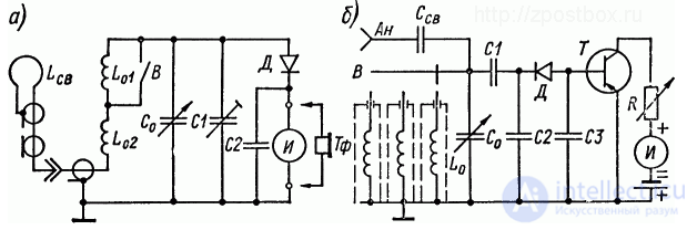
Fig. 17. Circuits of resonance frequency meters with voltage indicators and switchable coil-circuit inductors
If the oscillations under study are modulated, a high-resistance headphone Tf (Fig. 17, a) can serve as the indicator. Resonance is then noted by the greatest loudness of the tone at the modulating frequency. Such a frequency meter is suitable for aural monitoring of the quality of operation of radiotelephone transmitters.
Resonance frequency meters are characterized by their sensitivity, i.e. the minimum value of high-frequency power applied to them at which a clear indication of resonance is provided; this is usually within the range of 0.1-5 mW, rising to 0.1 W when an incandescent lamp is used. To increase sensitivity, a transistor DC amplifier with high input resistance is sometimes introduced into the resonance indicator (after the detector); the simplest circuit of such an amplifier is shown in Fig. 17, b.
At microwave frequencies, circuits made of lumped-constant elements become ineffective because of the sharp drop in their Q factor. In the frequency range from 100 to 1000 MHz, sufficiently good results are obtained with frequency meters having mixed-type circuits, with lumped capacitance and distributed inductance (Fig. 18). A curved section (turn) of silver-plated copper wire or tubing 2-5 mm in diameter is used as the inductance element L0. Switch B selects the measurement subrange. The frequency meter is tuned by changing the working length of the inductance turn L0 by means of a rotating contact slider. The upper limit of the measured frequencies is restricted by the value of the wiring capacitance Cmax. Coupling to the source of the oscillations under study is provided through a coupling turn L1.
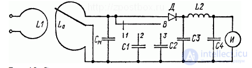
Fig. 18. Circuit of a resonance frequency meter with a mixed-type circuit
Fig. 19 shows the circuit of a wide-range, single-limit frequency meter with a coverage ratio in the range of 5-10; here the circuit's inductance element is a metal strip Pl, bent into an arc and connected to the stator St of the variable capacitor. A slider, mechanically and electrically linked to the capacitor's rotor Rot, slides along the strip. As the rotor turns, both the circuit's capacitance and its inductance increase (or decrease) simultaneously. In addition to their wide measurement range, such frequency meters have a fairly high Q factor combined with small dimensions. In the meter, decimeter and centimeter wavebands, instruments using oscillatory systems with distributed constants — sections of transmission lines and cavity resonators — are used for measuring the parameters of electromagnetic oscillations.
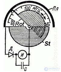
Fig. 19. Circuit of a wide-range, single-limit microwave resonance frequency meter
To improve the stability of the calibration characteristic, the elements of the frequency meter's circuit must have a strong, rigid construction and be made of materials with a low temperature coefficient. The largest error caused by the influence of external factors occurs when measuring the highest frequencies of each subrange, when the capacitance of capacitor C0 is small. To reduce this error, the initial circuit capacitance is sometimes increased by connecting a fixed or trimmer capacitor (C1 in Fig. 17, a) in parallel with capacitor C0. This reduces the frequency coverage ratio, which helps reduce the frequency-measurement error, but at the same time increases the number of subranges required. The measurement error is also reduced if the tuning control is operated through a vernier device with a reduction of several tens of times. In factory-made instruments, the vernier knob is often fitted with a scale divided into 100 divisions, while the main scale of the frequency meter's tuning control carries divisions marking the number of complete turns of the vernier knob. Using both scales together makes it possible to obtain several thousand reading points; the frequencies corresponding to them are determined with the aid of tables or graphs.
Retuning a frequency meter excited by a source of oscillations at frequency fx causes the current in its circuit to change according to the circuit's resonance curve (Fig. 20). The higher the Q factor of the circuit, the sharper its resonance curve, and the smaller the possible error in fixing resonance. To achieve a high Q factor, the circuit elements must have low losses, and the coupling of the circuit to the resonance indicator and to the source under study should be as weak as possible.
The coupling to the indicator can be reduced by using, for example, a capacitive voltage divider (Fig. 17, b) with a capacitance ratio C2/C1 >> 1. It should be kept in mind, however, that weakening the coupling to the circuit makes it necessary either to increase the sensitivity of the indicator or to strengthen the coupling to the source under study.
Using a straight-frequency-line capacitor in the frequency meter makes it possible to obtain an almost uniform frequency scale. Resonance frequency meters are calibrated by means of reference heterodyne frequency meters, while in the microwave range slotted measuring lines are used for this purpose. An approximate calibration can be performed using a test-signal generator or a transmitter with continuously variable frequency.
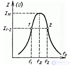
Fig. 20. Resonance curve of a resonance frequency meter
During measurements, the frequency meter or its coupling element is brought into the radiation field of the source under study. By adjusting their relative position, the coupling is set so that at resonance the indicator needle lies approximately at the middle of its scale.
With low frequency-meter sensitivity, the coupling to the source of oscillations has to be strengthened; this flattens the frequency meter's resonance curve, which makes it harder to accurately fix the state of resonance. To reduce the possible error, the two-reading method is used. After approximately tuning the frequency meter into resonance with the measured frequency fx, the circuit is detuned, by varying the capacitance C0, first to one side and then to the other side of the resonant frequency, until the same indicator reading (I1-2) is obtained, approximately within 50-70% of the resonant value Imax (Fig. 20). Since the steep slopes of the resonance curve are used in this process, the tuning frequencies f1 and f2 of the circuit corresponding to that current can be determined with high accuracy. The measured frequency fx = (f1 + f2)/2.
If the oscillations under study are non-sinusoidal, it is possible to tune the frequency meter to one of the harmonics. In this case the frequency meter will also detect tuning at a number of other frequencies that are multiples of the fundamental oscillation frequency. The latter is determined as the lowest of the series of resonant frequencies found.
If the EMF induced in the frequency meter's circuit is insufficient for the normal operation of the resonance indicator, the measurement can be carried out by the reaction (absorption) method: tuning to resonance is determined from the effect of the frequency meter on the operating mode of the generator, from which the measuring circuit absorbs some energy. A sufficiently strong coupling is established between the circuits of the generator and the frequency meter, and the tuning of the latter is smoothly varied. At resonance, the DC component of the generator's anode (or collector) current reaches a maximum, while the DC component of the control-grid (or base) current drops sharply, which can be detected by connecting a sensitive DC meter into one of the circuits mentioned. The frequency meter does not affect the frequency of the generated oscillations, because at resonance it introduces only a resistive (active) component into the generator's circuit.
A resonance frequency meter is a passive-action instrument, since its operation is based on absorbing energy from the source of the measured frequency. It is therefore unsuitable for directly measuring the tuning frequency of radio receivers and isolated oscillatory circuits. However, the carrier frequency of the radio station to which a receiver is tuned can be measured quite accurately by the reaction method. To do this, the frequency meter's circuit is coupled to the receiver's antenna circuit by means of a coupling coil inserted into that circuit, or by bringing it close to a magnetic (loop) antenna. The frequency meter's tuning is varied until resonance is obtained, which is detected by a sharp drop in the loudness of the audio signals reproduced by the receiver.
The operating principle of heterodyne frequency meters is based on comparing the frequency of the input signal with the frequency of a tunable auxiliary oscillator (the heterodyne, or local oscillator) using the so-called zero-beat method; the procedure for working with them is similar to that used with resonance frequency meters.
Heterodyne frequency meters are used for precise frequency measurements over a continuously variable range of high frequencies. In principle, a heterodyne frequency meter differs from a crystal calibrator built to the functional diagram in Fig. 12 only in that, instead of a crystal oscillator, it uses a heterodyne, i.e. a low-power oscillator with a continuously adjustable tuning frequency. The presence of a mixer allows the instrument to be used not only for calibrating the frequency scales of radio receivers, but also for measuring the frequency of generators by the zero-beat method. Zero beats are indicated by headphones, oscilloscopic and electron-ray (magic-eye) indicators, as well as pointer-type meters.
The measurement error of a heterodyne frequency meter is mainly determined by the stability of the heterodyne frequency and the error in setting it. For this reason the heterodyne is often preferred to be built using electron tubes. Frequency stability is improved by a proper choice of the heterodyne's circuit and design, the use of components with a low temperature coefficient, the inclusion of a buffer stage between the heterodyne and the output circuits, stabilization of the supply voltages, and a long warm-up of the instrument under power before measurements. To improve the smoothness of adjustment and the accuracy of frequency setting, the heterodyne's tuning capacitor is usually controlled through a vernier mechanism with a large reduction ratio (up to 100-300 times). Direct reading of frequency from the variable capacitor's scale is done only in the simplest designs; in most instruments the scale is made uniform with a very large number of divisions (up to several thousand), and the reading is converted into frequency using tables or graphs.
To reduce the number of frequency subranges and improve frequency stability, heterodynes usually operate in a narrow band of comparatively low frequencies (with an overlap coefficient of two), and both the fundamental frequencies of the generated oscillations and a number of their harmonics are used for measurements; the appearance of the latter is ensured by an appropriate choice of the operating mode of the heterodyne or the buffer amplifier. For example, in the widely used Ch4-1 frequency meter, with an overall measured-frequency range from 125 kHz to 20 MHz, the heterodyne has two smooth fundamental-frequency subranges: 125-250 kHz and 2-4 MHz. On the first subrange, using the first, second, fourth and eighth harmonics, it is possible to smoothly cover the frequency band 125-2000 kHz; on the second subrange, using the first, second, fourth and partly the fifth harmonics, the frequency band 2-20 MHz is covered. Thus each position of the heterodyne's tuning knob corresponds to three or four working frequencies, whose values can be found from the calibration table. For example, the frequencies 175, 350, 700 and 1400 kHz are all measured at one and the same heterodyne setting, at the fundamental frequency fg = 175 kHz.
The multi-valued nature of the heterodyne's tuning frequencies creates the possibility of an error in identifying the harmonic with which the oscillations of the measured frequency fx produce beats. Therefore, before starting measurements, it is necessary to know the approximate value of the frequency fx. However, the latter can also be determined by calculation using the heterodyne frequency meter itself.
Suppose that, as the heterodyne's tuning is varied, zero beats with the frequency fx are obtained at two adjacent values of the fundamental frequencies fg1 and fg2 within the same heterodyne subrange. Obviously the frequency fx is simultaneously a harmonic of both these frequencies, i.e.
fx = n*fg1 = (n+1)*fg2.
where n and (n + 1) - are the harmonic numbers for the fundamental frequencies fg1 and fg2 respectively (with fg2 < fg1).
Solving the resulting equation for n, we find
n = fg2/(fg1-fg2).
Consequently, the measured frequency
fx = n*fg1 = fg1*fg2 / (fg1-fg2).
For example, if zero beats are obtained at the fundamental frequencies fg1 ≈ 1650 kHz and fg2 ≈ 1500 kHz, then approximately fx ≈ 1650*1500/(1650 - 1500) = 16500 kHz.
When measuring frequency, care should be taken to avoid an error caused by the possible occurrence of beats between the heterodyne's oscillations and a harmonic of the measured frequency; measurements should therefore be carried out with loose coupling between the frequency meter and the generator under test. The measurement error also increases when the instrument is exposed to modulated oscillations; in this case the beats at the fundamental (carrier) frequency will be heard against a noise background of beats with the sideband frequencies.
Heterodyne frequency meters of the type discussed provide measurement of high frequencies with an error of about 1%. Reducing the measurement error to 0.01% or less is achieved by adding a crystal oscillator to the frequency meter, which allows the heterodyne's scale to be checked and corrected at a number of reference points before starting measurements.
A detailed functional diagram of a high-precision heterodyne frequency meter is shown in Fig. 15. The heterodyne has two subranges, whose adjustment is performed by trimmer capacitors C3 and C4. The fundamental oscillation frequency is set by the straight-frequency variable capacitor C1. The level of the input (output) signal is adjusted by potentiometer R. The crystal oscillator produces oscillations rich in harmonics, whose fundamental frequency is often taken as 1 MHz. Selection of the instrument's mode of operation is carried out without disturbing the inter-stage couplings, by switching the power to individual components on or off. When switch B2 is set to position 3 (“Crystal”), the heterodyne is switched off and the crystal oscillator is switched on; the frequency meter can then be used as a crystal calibrator for frequency measurements on the generator's harmonics. In switch position 1 (“Heterodyne”), conversely, the crystal oscillator is switched off and the heterodyne is switched on. This is the normal operating mode of the frequency meter.
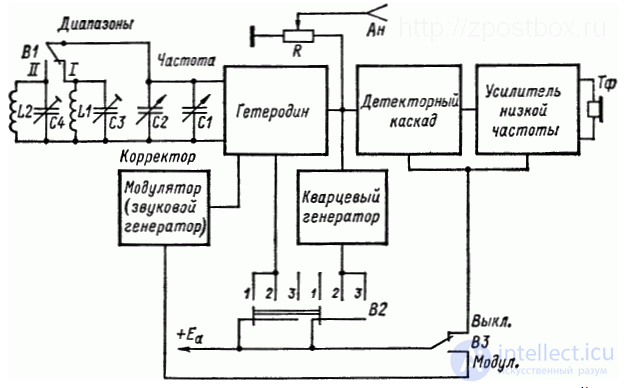
Fig. 15. Functional diagram of a high-precision heterodyne frequency meter
Checking of the heterodyne's frequency scale is performed by setting switch B2 to position 2 (“Check”), when both the heterodyne and the oscillator are switched on simultaneously, and their oscillations are fed to the detector. At a certain ratio of the frequencies or harmonics of these oscillations, audio-frequency beats arise, whose frequency is determined by the formula
F = |m*fg - n*fk|,
where fg and fk - are the fundamental frequencies of the heterodyne and the crystal oscillator respectively, and m and n - are integers corresponding to the numbers of the interacting harmonics.
The beat frequency turns out to be zero (F = 0) for a number of frequencies in the heterodyne's range that satisfy the condition
fg =(n/m)*fk.
These frequencies are called reference frequencies and are specially highlighted in the calibration tables. Let us find, as an example, the reference frequencies (f0) of the heterodyne range 2000-4000 kHz, given that the fundamental frequency of the crystal oscillator is fk = 1000 kHz:
at m = 1 and n = 2, 3 and 4 f0 = 2000, 3000 and 4000 kHz; at m = 2 and n = 5 and 7 f0 = 2500 and 3500 kHz;
at m = 3 and n = 7, 8, 10 and 11 f0 = 2333, 2667, 3333 and 3667 kHz, etc.
It should be kept in mind that as the numbers of the interacting harmonics increase, the amplitude of the beats decreases.
If the calibration of the heterodyne's scale has been disturbed, then when its tuning knob is set to one of the reference frequencies and the crystal oscillator is switched on, instead of zero beats, audio-frequency oscillations are produced, which after amplification are heard in headphones Tf. Correction (calibration) is performed using a small-capacitance capacitor C2, connected in parallel with the main tuning capacitor C1: with its help, before starting measurements, zero beats are obtained at the reference point closest to the frequency being measured.
Let us consider the procedure for tuning a heterodyne frequency meter using the following example. Suppose it is required to check the accuracy of a transmitter's scale at a frequency of 10700 kHz. Referring to the frequency meter's calibration table, we find that this frequency corresponds to a fundamental frequency of 10700/4 = 2675 kHz. From the table or the scale of reference points we determine that the nearest reference frequency is 2667 kHz. We then set the frequency 2667 kHz on the C1 capacitor's scale and, having set switch B2 to position “Check” (2), obtain zero beats with the corrector C2. We then set switch B2 to position “Heterodyne” (1) and, having set the heterodyne frequency to 2675 kHz, carry out the transmitter scale check at this frequency.
When measuring an unknown frequency fx, calibration of the heterodyne scale is performed at the reference point closest to the expected value of this frequency, and then, in measurement mode, zero beats are obtained by adjusting the heterodyne frequency.
When calibrating the heterodyne scale, as well as when measuring the frequency of generators, the modulator must be switched off; when measuring the tuning frequency of receivers, the instrument's low-frequency unit is not needed. Switch B3 is used to switch off the frequency meter's unused components.
Heterodyne frequency meters of various industrially manufactured types together cover a measured-frequency band from 100 kHz to 80 GHz, with a measurement error within +-(5*10-4...5*10-6). At very high frequencies it is difficult to obtain zero beats. For this reason, in microwave frequency meters a low-frequency frequency meter (for example, a capacitor type) is sometimes used as an indicator; it is used to determine the beat difference frequency F, and a correction for its magnitude is introduced into the measurement results.
A very small measurement error over a very wide frequency range (from low to super-high frequencies) is achieved by combining two frequency meters: a heterodyne and an electronic-counting one. The latter, besides its independent use over its own frequency range, can be used for the precise measurement of the heterodyne's tuning frequency when zero beats are reached; in this case a crystal oscillator, calibration tables and graphs become unnecessary.
Electronic capacitor frequency meters are used to measure frequencies in the range from 10 Hz to 1 MHz. The principle of such frequency meters is based on the alternating charging of a capacitor from a battery with its subsequent discharge through a magnetoelectric mechanism. This process takes place at a frequency equal to the measured frequency, since the switching is driven by the voltage under test itself. During one cycle, a charge Q = CU will flow through the magnetoelectric mechanism; consequently, the average current flowing through the indicator will be equal to I_avg=Qf_x=CUf_x. Thus, the reading of the magnetoelectric ammeter turns out to be proportional to the measured frequency. The intrinsic fiducial error of such frequency meters lies within 2-3%.
Capacitor frequency meters, which implement the method of charging and discharging a reference capacitor, also belong to the Ch4- group. The operating principle consists in measuring the current of a capacitor that is alternately switched between charge and discharge at the measurement frequency (Fig. 41).
Capacitor C0, using a key (position 1), is charged from source GB through a current-limiting resistor R up to voltage U1, and is discharged through a magnetoelectric instrument (position 2) down to U2 .
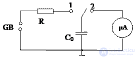
Fig. 41
Consequently, the amount of electric charge delivered to the capacitor and given up to the instrument during one switching cycle is  , where D
U=U1-U2 . If the switching frequency per 1 second is equal to fx , then 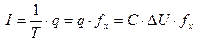 , i.e. the current flowing through the instrument is directly proportional to fx .
Frequency meters of this type are used at frequencies of 10-106 Hz and provide an error of 2-3%. To increase measurement accuracy, calibration oscillators of reference frequency are built into the frequency meters. As an example we may cite the Ch4-7 frequency meter.
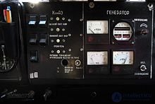
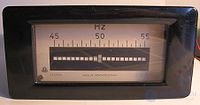
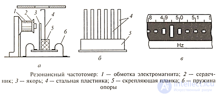
It is an instrument with a moving part in the form of a set of elastic elements (strips, reeds) that are driven into resonant vibration by an alternating magnetic or electric field. Most often an electromagnet is used to excite the vibrations, with steel strips serving as the elements. The element whose natural frequency is closest to the frequency of the current flowing through the electromagnet's winding goes into resonance and vibrates with the largest amplitude, which is displayed visually.
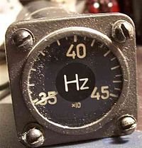
By the measuring mechanism used, analog frequency meters are of the electromagnetic, electrodynamic and magnetoelectric systems. Their operation is based on the use of a frequency-dependent circuit whose impedance magnitude depends on frequency. The measuring mechanism is usually a ratiometer (logometer), to one arm of which the measured signal is applied through a frequency-independent circuit, and to the other — through a frequency-dependent one; as a result of the interaction of the magnetic fluxes, the ratiometer's rotor with its pointer settles into a position that depends on the ratio of the currents in the windings. Analog frequency meters operating on other principles also exist.
Frequency can be measured as the quantity that is the reciprocal of the signal period
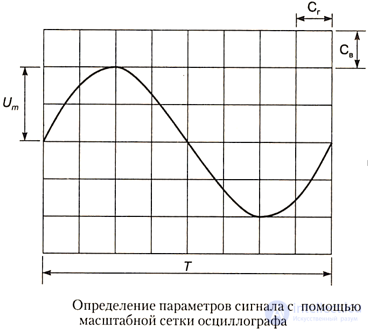
Oscilloscope method (Lissajous figure method)
The signals of the measured frequency fx and the reference frequency f0 are applied to channels Y and X respectively. By varying the reference frequency, a stationary figure is made to appear on the screen.
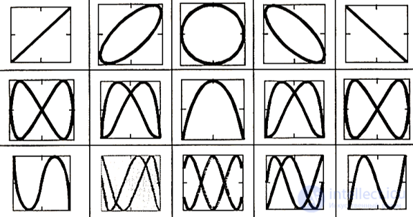
To determine fx, horizontal and vertical tangents to the figure are drawn and the number of tangencies n with the horizontal and vertical is counted. The frequency ratio is determined as the ratio of the number of tangencies with the vertical to the number of tangencies with the horizontal f0/fx=nB/ng.
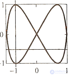
Oscilloscope methods belong to the laboratory methods of frequency measurement.
Their error is 1.5-2.0 %.

Comments