Lecture
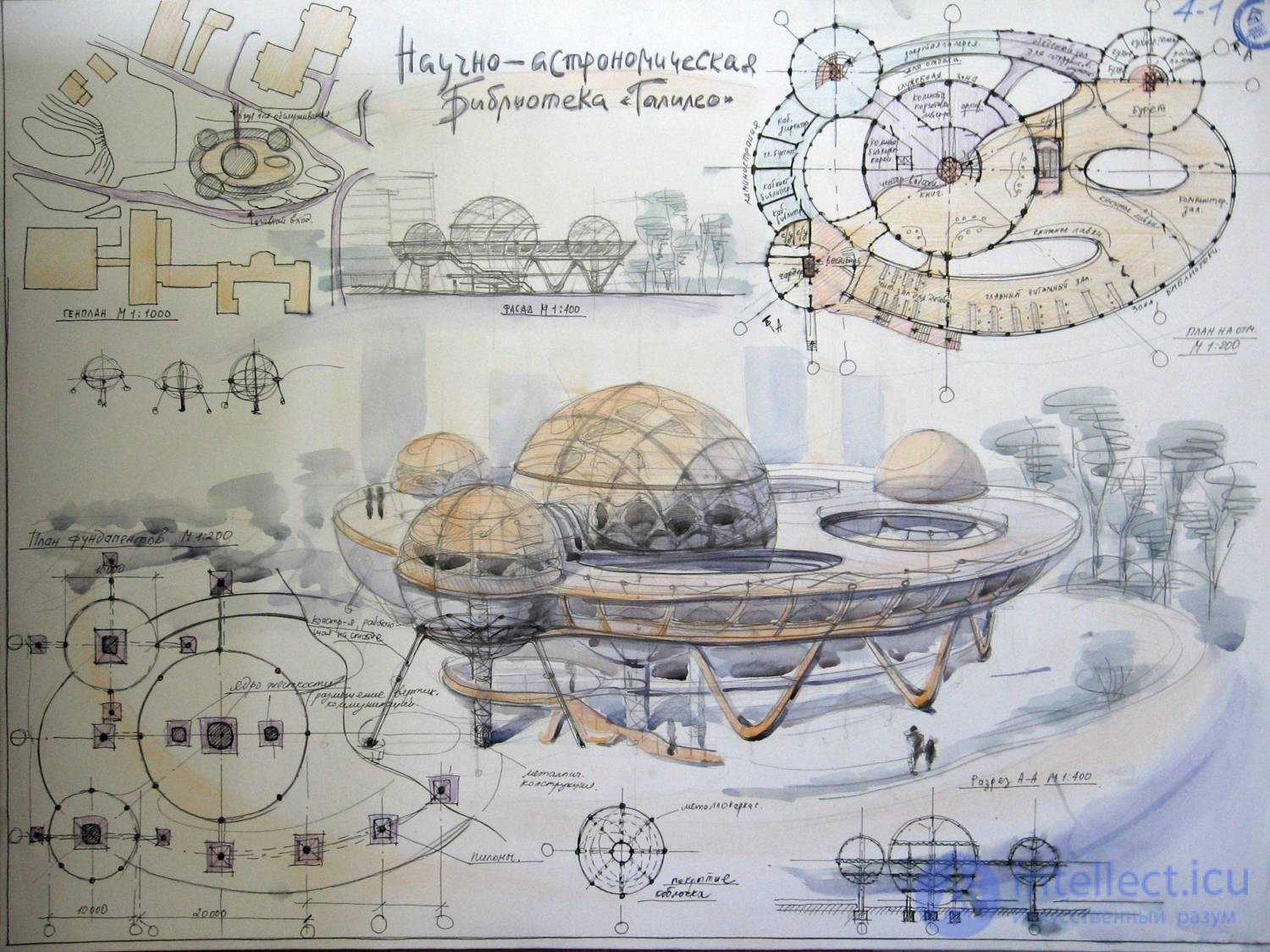
architectural graphics is a branch of fine art that encompasses the creative process of presenting ideas and images in the field of engineering and architectural design. It is a detailed development of a plan of a future building in a drawing with a scale (or a garden for a landscape architect) using conventional symbols of future foundations, walls, pylons or columns, with a mark of future windows and doors. A general plan allows you to show the location of a building or an ensemble of buildings on the ground, indicating the cardinal directions. An architect's drawing is closely related to mathematical calculations and indications of the dimensions of the future building, the ratio of its parts (scale). It is used both in the design of new buildings and in the development of fixation plans for existing or destroyed buildings.
The first drawings were created in Ancient Egypt , where a strong school of mathematicians and geometers was formed.
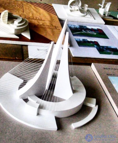
The design of an architectural object cannot be done without the pictorial representation of the architect’s ideas in graphics and volumetric models.
Let's take a closer look at the types of architectural graphics
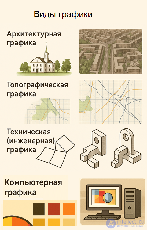
Architectural graphics cover a wide range of visual means used to express ideas, forms and spaces in architecture. Here are the main types of architectural graphics, classified by purpose and technique:
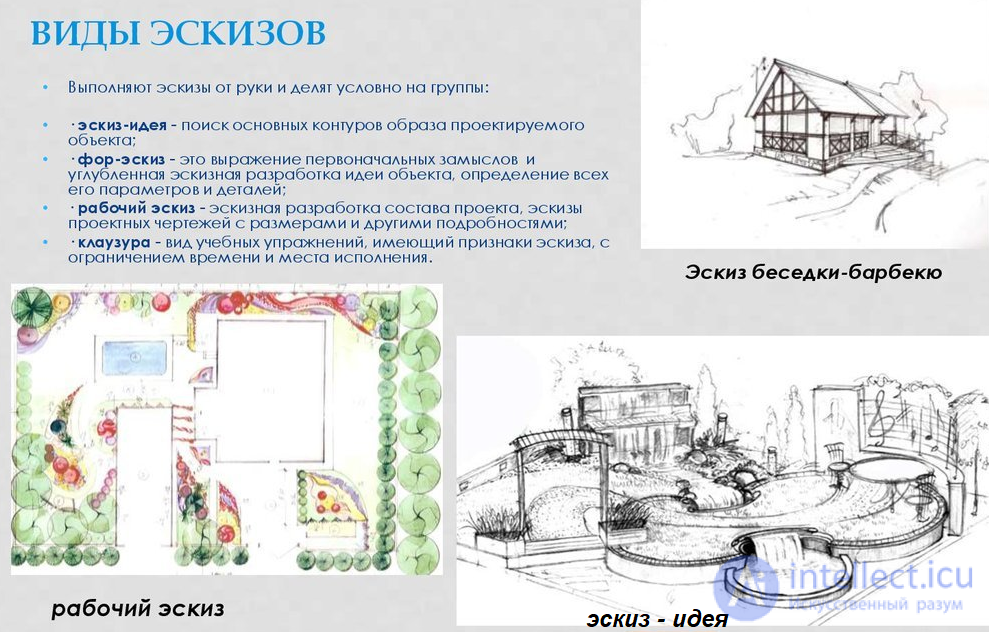
Sketch graphics are quick sketches that reflect the idea, mood or composition of a future object.
Project graphics include plans, facades, sections , made according to the rules of descriptive geometry.
Working drawings are precise technical documents for construction, with dimensions, materials and components.
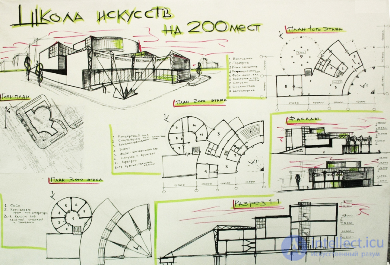
Demonstration graphics are visualizations for presenting a project to a customer or the public.
Architectural drawing is artistic depictions of buildings, interiors, or urban scenes, often done by hand.
Linear graphics - the construction of an image using lines and hatching (pencil, ink, pen).
Tonal graphics - the transmission of light and shadow and volume using shades (watercolor, gouache, pastel).
Colour graphics - the use of rich colours, often combined with collages or digital media.
Digital graphics – creating images using programs (AutoCAD, Revit, Photoshop, SketchUp, etc.).
Classic graphics - manual techniques: watercolor, ink, pencil, gouache, pen.
Clausura is a study sketch completed in a limited amount of time.
Entourage and staffage - adding people, trees, furniture to liven up the scene.
Architectural fantasy - free, unrealistic compositions, often with elements of imagination.
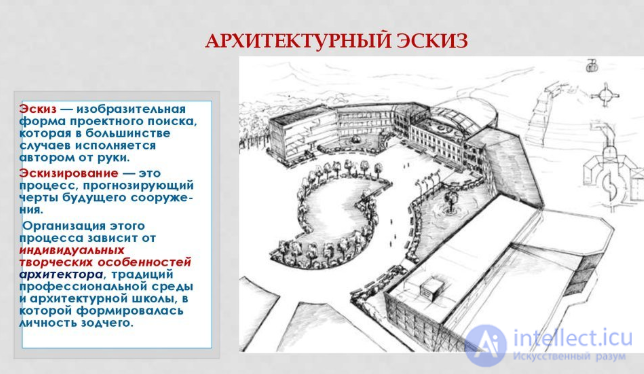
A sketch is a visual form of project search, which in most cases is done by hand by the author. Sketching is a process that predicts the features of a future building. The organization of this process depends on the individual creative characteristics of the architect, the traditions of the professional environment and the architectural school in which the architect's personality was formed.
DRAWING
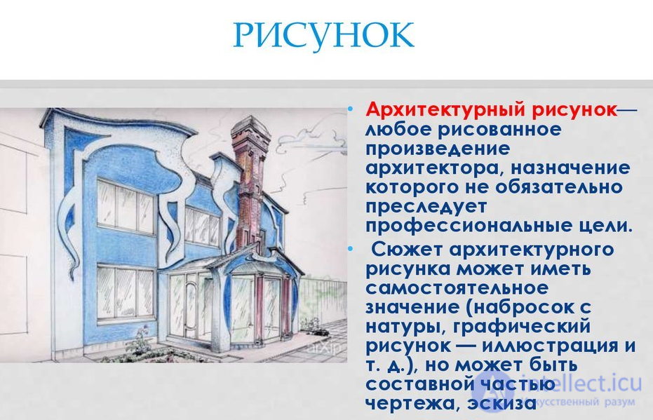
• An architectural drawing is any drawn work by an architect, the purpose of which does not necessarily pursue professional goals.
• The subject of an architectural drawing can have an independent meaning ( a sketch from life, a graphic drawing - illustration, etc.), but can be
an integral part of a drawing, sketch
EXPLORATORY SKETCH
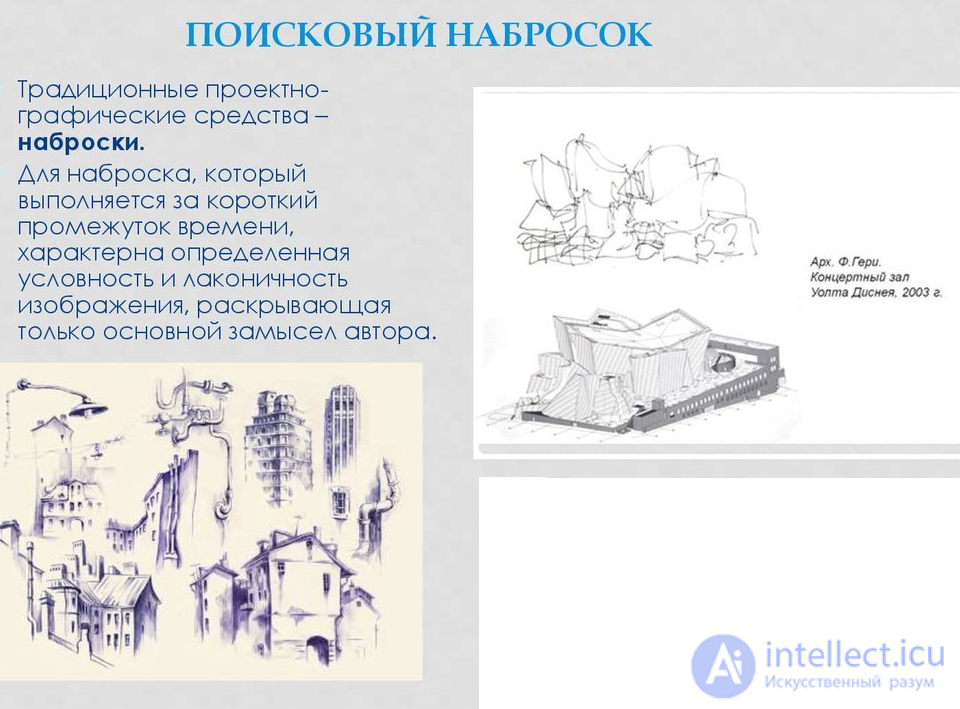
• Traditional design-graphic means – sketches.
• A sketch, which is completed in a short period of time, is characterized by a certain conventionality and laconicism of the image, revealing only the main idea of the author.
SEARCH DRAWING
• In a search drawing, an image of the designed object, its parts and individual units, monochrome with the use of a minimum of pictorial means
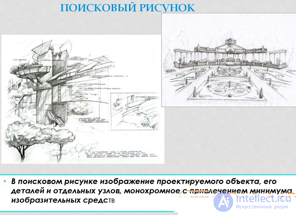
The task of identifying architectural and design features is well performed by a drawing. Detailed drawing of a house An architectural drawing is an image that conveys information about the size, shape and design of an object.
A drawing is a conventional image of an object (building, structure or construction), made according to certain rules using drawing tools or software.
The drawing shows several views of the product. Views are made based on how the product is observed: from the front, from above or from the left (side), plans, sections, projections.
TYPES OF DRAWING
Drawing is used at all stages of design work, each of which has its own style of drawing graphics.
Drawing types:
In modern drawing, the construction of an object is necessarily carried out according to the laws of descriptive geometry.
Often objects are depicted enlarged or reduced in comparison with the original. But despite this, the dimensions on the drawing are indicated as real.
The number that shows how many times the actual dimensions are reduced or increased is called the scale.
A sketch is a hand-drawn image of an object, using the same rules as a drawing, but without observing the exact scale. When drawing a sketch, the relationship between the parts of the object is maintained.
A technical drawing is a visual representation of an object, made by hand with the same lines as the drawing, indicating the dimensions and material from which the object is made.
It is constructed approximately, by eye, maintaining the relationships between the individual parts of the object.
The number of views on the drawing (sketch) should be such as to give a complete idea of the shape of the object.
SCANNING PATTERNS
scan – a drawing of a flat blank from which the three-dimensional shape of a structure is folded
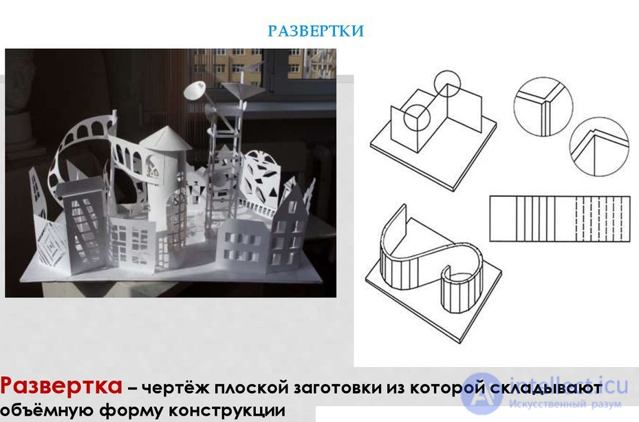
Volumetric modeling allows you to view the structure from any angle. Objects of volumetric architecture are presented as a single volume, or a fused form, or as a group of separate parts,
There are certain rules for setting dimensions.
The size (in millimeters) is indicated above the dimension line from left to right and from bottom to top. The name of the units of measurement is not indicated.
The thickness of the part is indicated by the Latin letter S; the number to the right of this letter shows the thickness of the part in millimeters.
Certain rules also apply to the designation of the hole diameter on the drawing - it is designated by the symbol Ø.
The radii of circles are designated by the Latin letter R; the number to the right of this letter shows the radius of the circle in millimeters.
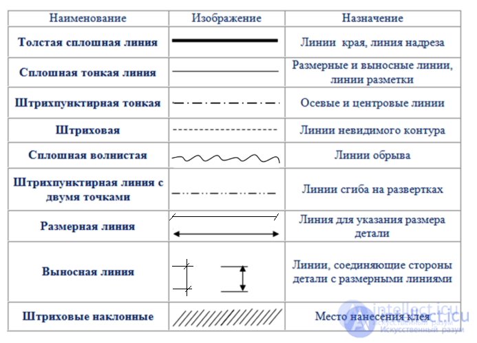
The outline of the part on the drawing (sketch) must be shown with solid thick main lines (visible contour lines)
; dimension lines - solid thin; invisible contour lines - dashed; axial - dash-dotted, etc.
A building or any structure in the plan is divided by conventional axial lines into a number of segments. These lines, which determine the position of the main supporting structures, are called longitudinal and transverse coordination axes.
The interval between the coordinate axes in the building plan is called a step, and in the predominant direction the step can be longitudinal or transverse.
Marking of the coordinate axes
If the distance between the longitudinal coordinate axes coincides with the span, floor or roof of the main supporting structure, then this interval is called a span.
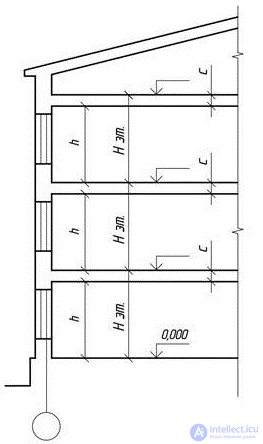
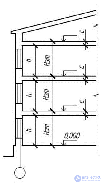
Floor height in a multi-story residential building
The height of the floor H is taken as the distance from the floor level of the selected floor to the floor level of the floor above. The height of the upper floor is determined by the same principle, and the thickness of the attic floor is taken as conditionally equal to the thickness of the interfloor floor c. In industrial single-story buildings, the height of the floor is equal to the distance from the floor to the lower surface of the roof structure.
In order to determine the relative position of parts of a building, a grid of coordinate axes is used, defining the supporting structures of a given building.
The coordinate axes are drawn with thin dashed lines and marked inside circles with a diameter of 6 to 12 mm.
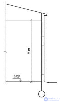
Floor height in a one-story building
The marking of the coordination axes is done using Arabic numerals and capital letters, with the exception of the symbols: 3, Й, О, Х, Ы, Ъ, Ь.
The height of the font indicating the coordinate axes is selected to be one or two numbers larger than the size of the numbers on the same sheet.
The numbers indicate the axes on the side of the building with the largest number of coordinate axes.
The direction of axis marking is from left to right, horizontally and from bottom to top, vertically.
Axis markings are usually located on the left and bottom sides of the building plan.
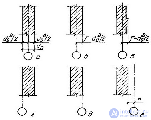
The coordinate axis of the external wall is located at a distance of a = 100 mm, observing the indentation for the installation of floor slabs.
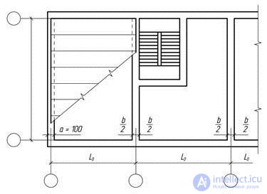
Coordination axes of external and internal walls
The construction of the main elements of buildings is carried out using the modular coordination of sizes in construction (MKRS), according to which the dimensions of the main space-planning elements of the building must be multiples of the module.
The main module is taken to be 100 mm.
The main structural elements (load-bearing walls, columns) of the building are located along the modular coordination axes (longitudinal and transverse). The distance between the coordination axes in low-rise buildings is taken to be multiples of the 3M module (300 mm).
To determine the relative position of the building elements, a grid of coordination axes is used.
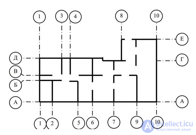
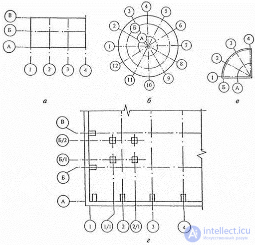
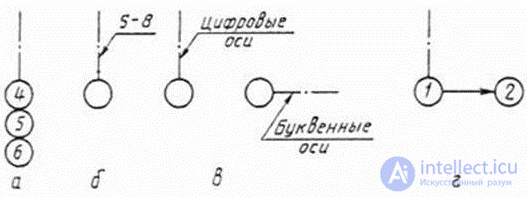
The coordination axes are applied with thin dash-dotted lines and are designated, as a rule, on the left and bottom sides of the plan, marked, starting from the lower left corner, with Arabic numerals (from left to right) and capital letters of the Russian alphabet (from bottom to top) in circles with a diameter of 6 ... 12 mm (Fig. 2).
Fig. 2. Example of marking of coordination axes
Dimensions on construction drawings are given in millimetres and are usually applied in the form of a closed chain.
Dimension lines are limited by notches — short strokes 2 … 4 mm long, drawn at an angle to the right at 45° to the dimension line. Dimension lines should extend beyond the extreme extension lines by 1 … 3 mm. The dimension number is located above the dimension line at a distance of 1 … 2 mm (Fig. 3, a).
To indicate the position of the cutting plane of the section or section of the building, an open line in the form of separate thick strokes with arrows indicating the direction of view is used. The section line is designated by Arabic numerals (Fig. 3, c). The initial and final strokes should not intersect the contour of the image.
The dimensions of buildings by height (floor heights) are assigned as multiples of modules. The height of a building floor is defined as the distance from the floor level of a given floor to the floor level of the floor above. In residential building projects, the floor height is taken to be 2.8; 3.0; 3.3 m.
On facades and sections, elevation marks of the level of an element or structure of a building from any calculated level taken as zero are applied. Most often, the zero level (mark ±0.000) is taken as the finished floor level (floor covering) of the first floor.
Level marks are indicated in meters with three decimal places without designation of units of length and are placed on extension lines in the form of an arrow with a shelf. The sides of the right angle of the arrow are drawn as a solid thick main line at an angle of 45° to the extension line (Fig. 4).
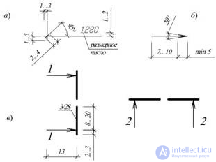
Fig. 3. Drawing of dimensions and positions of cuts:
a – dimensions and dimension lines; b – arrows of the direction of view;
c – positions of sections
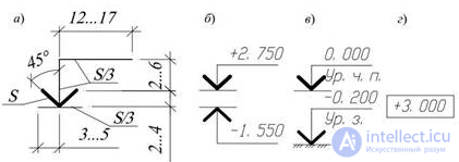
Fig. 4. Applying level marks on views:
a – dimensions of the level mark sign; b – examples of the location and design of
level signs on sections and cross-sections; c – the same, with explanatory inscriptions;
d – example of the image of the level sign on plans
The elevation sign may be accompanied by explanatory inscriptions: Ур.ч.п. — finished floor level; Ур.з. — ground level.
The elevations on the plans are applied in rectangles (Fig. 4, г). Elevations above the zero level are designated with a plus sign (e.g. + 2.700), below zero — with a minus sign (e.g. — 0.200).
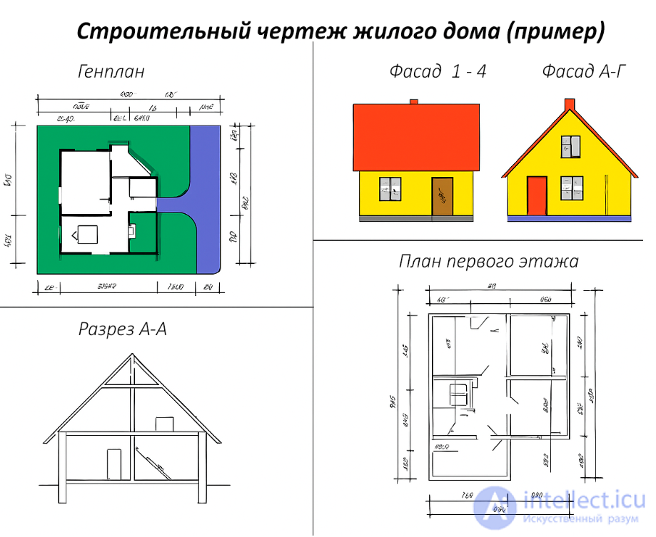
The following names of building types are accepted in construction drawings.
The name of the building plans shall indicate the elevation of the finished floor of the floor, the floor number or the designation of the corresponding plane; when completing a part of the plan — the axes limiting this part, for example:
Plan at elevation +3.000;
Plan of the 2nd floor;
Plan 3–3;
Plan at elevation 0.000 in axes 21–39, A–D.
The name of the building sections shall indicate the designation of the corresponding cutting plane (in Arabic numerals), for example, Section 1–1.
The names of building facades indicate the extreme axes between which the facade is located, for example:
Facade 1–5;
Facade 12–1;
Facade A–G.
For multilayer structures, extension inscriptions are made, located on the shelves of a straight line
ending with an arrow (Fig. 5). The sequence of inscriptions (material or structure of layers with an indication of their thickness) for individual layers must correspond to the sequence of their location on the drawing from top to bottom and from left to right.
Additional explanations to the drawing or position numbers of elements in the specification are placed on extension lines ending with a shelf.
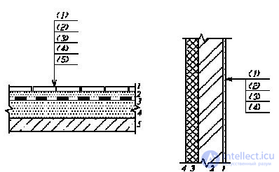
Fig. 5. Examples of execution of extension inscriptions
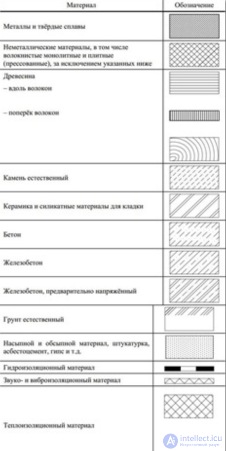
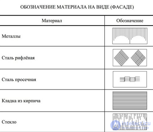
Graphic symbols of materials in sections and cross-sections of buildings and structures are given in Appendix 3. The distance between parallel hatching lines is selected within 1 ... 10 mm depending on the hatching area and the scale of the image. Material symbols are not used on drawings if the material is homogeneous, if the dimensions of the image do not allow the application of the symbol.
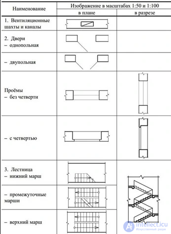
Conventional graphic images of building elements and sanitary devices are given in Appendix 4.
GRAPHIC DESIGNATION OF MATERIALS IN SECTIONS, CROSS-SECTIONS AND VIEWS
GRAPHIC IMAGES OF BUILDING ELEMENTS
A building or any structure in the plan is divided by conventional axial lines into a number of segments. These lines, which determine the position of the main supporting structures, are called longitudinal and transverse coordination axes.
The interval between the coordinate axes in the building plan is called a step, and in the predominant direction the step can be longitudinal or transverse.
If the distance between the longitudinal coordinate axes coincides with the span, floor or roof of the main supporting structure, then this interval is called a span.
The height of the floor H is taken as the distance from the floor level of the selected floor to the floor level of the floor above. The height of the upper floor is determined by the same principle, and the thickness of the attic floor is taken as conditionally equal to the thickness of the interfloor floor c. In industrial single-story buildings, the height of the floor is equal to the distance from the floor to the lower surface of the roof structure.
In order to determine the relative position of parts of a building, a grid of coordinate axes is used, defining the supporting structures of a given building.
The coordinate axes are drawn with thin dash-dotted lines and marked inside circles with a diameter of 6 to 12 mm. The diameter of the circles should correspond to the scale of the drawing: 6 mm - for 1:400 and less; 8 mm - for 1:200 - 1:100; 10 mm - for 1:50; 12 mm for 1:25; 1:20; 1:10. The direction of the axis marking is from left to right, horizontally and from bottom to top, vertically.
If the coordination axes of the opposite sides of the plan do not coincide, the designations of the said axes at the points of divergence are additionally applied along the upper and/or right sides. For individual elements located between the coordination axes of the main load-bearing structures, additional axes are applied and designated as a fraction:
It is permitted to assign digital and letter designations to the coordination axes of half-timbered columns in continuation of the designations of the axes of the main columns without an additional number.
The binding of the coordinate axes occurs according to the rules described in paragraph 4 of GOST 28984-91. Example:
The connection of load-bearing walls made of piece materials to the coordinate axes should be carried out in compliance with the following rules:
When supporting floor slabs across the entire thickness of the load-bearing wall, it is permissible to align the outer coordination plane of the walls with the coordination axis (Fig. 9g).
The marking of the coordination axes is made with Arabic numerals and capital letters, with the exception of the symbols: 3, Й, О, Х, Ы, Ъ, Ь. The numbers indicate the axes on the side of the building with the largest number of coordination axes. The marking of the axes is usually located on the left and lower sides of the building plan. The height of the font indicating the coordination axes is selected one or two numbers higher than the size of the numbers on the same sheet. Gaps in the digital and letter designations of the coordination axes are not allowed.
In the image of a repeating element linked to several coordinate axes, the coordinate axes are designated in accordance with the figure:
If necessary, the orientation of the coordinate axis to which the element is attached, in relation to the adjacent axis, is indicated in accordance with the figure.
Rules for the preparation of drawings of plans in accordance with the requirements of the Unified System for Design Documentation (ESKD) and the Schematic Drawing of Plans (SPDS):
The process of displaying three-dimensional objects is more complex than the corresponding two-dimensional process. In the two-dimensional case, a window is simply defined in two-dimensional world coordinate space and output fields are defined on a two-dimensional view surface. In general, objects described in world coordinates are cut off at the boundary of the visible volume, and then converted into an output field for the display. The complexity characteristic of the three-dimensional case arises because the view surface does not have a third dimension; various types of projections are used for this.
In general, projections transform points given in a coordinate system of dimension n into coordinate systems of dimension less than n.
We will consider the case of projection of three dimensions into two. The projection of a three-dimensional object (represented as a set of points) is constructed using direct projection rays, which are called projectors and which pass through each point of the object and, intersecting the picture plane, form a projection.
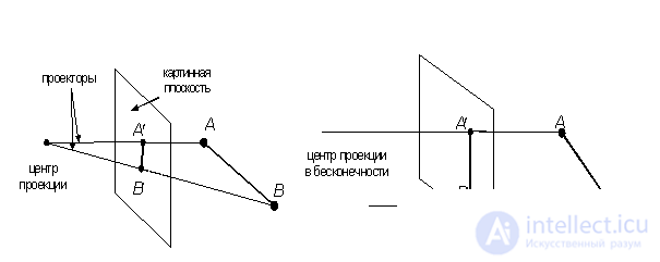
Fig. 3.7. Central and parallel projections
The class of projections thus defined is called flat geometric projections, since the projection is made onto a plane rather than a curved surface, and straight rather than curved lines are used as projectors.
Many map projections are either non-planar or non-geometric.
In the future, flat geometric projections will be called simply projections.
Projections are divided into two main classes (Fig. 3.7):
· parallel (axonometric);
· central (perspective).
A complete classification of projections is shown in Fig. 3.8.
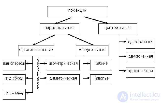
Fig. 3.8. Classification of projections
Parallel projections are divided into two types depending on the relationship between the projection direction and the normal to the projection plane (Fig. 3.9):
1) orthographic – the directions coincide, i.e. the projection direction is normal to the projection plane;
2) oblique – the projection direction and the normal to the projection plane do not coincide.
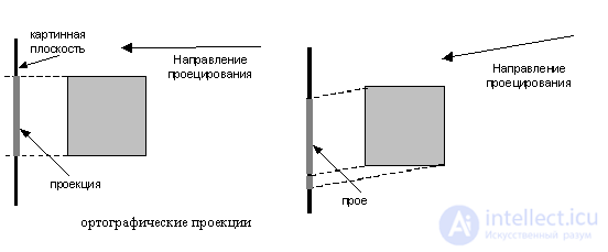
Fig. 3.9. Orthographic and oblique projections
The most widely used types of orthographic projections are the front view, the top view (plan) and the side view, in which the picture plane is perpendicular to the principal coordinate axes. If the projection planes are not perpendicular to the principal coordinate axes, then such projections are called axonometric.
In axonometric projection, the parallelism of lines is maintained, but angles are changed; distance can be measured along each of the main coordinate axes (in general, with different scale factors).
An isometric projection is a normal to the projection plane (and hence the direction of projection) that makes equal angles with each of the principal coordinate axes. If the normal to the projection plane has coordinates (a,b,c), then we require that |a| = |b| = |c|, or ±a=±b=±c, i.e. there are 8 directions (one in each octant) that satisfy this condition. However, there are only 4 different isometric projections (if we do not consider hidden line removal), since the vectors (a, a, a) and (-a,-a,-a) define normals to the same projection plane.
The isometric projection (Fig. 3.10.) has the following property: all three main coordinate axes are shortened equally. Therefore, measurements can be taken along the direction of the axes with the same scale. In addition, the main coordinate axes are projected so that their projections form equal angles with each other (120°).
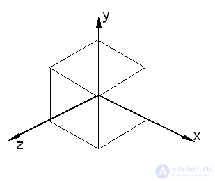
Fig. 3.10. Isometric projection of the unit cube
Oblique projections combine the properties of orthographic projections (front, top, and side views) with the properties of axonometry. In this case, the projection plane is perpendicular to the principal coordinate axis, so the side of the object parallel to this plane is projected so that angles and distances can be measured. Projecting other sides of the object also allows for linear measurements (but not angular measurements) along the principal axes. Note that the normal to the projection plane and the projection direction do not coincide.
Two important types of oblique projections are:
· Cavalier – horizontal oblique isometry (military perspective);
· Cabine (cabinet) – frontal oblique diameter.
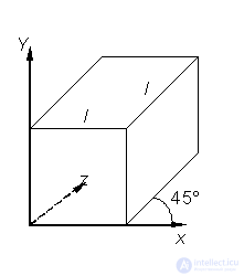
Fig. 3.11. Cavalier projection
In the Cavalier projection (Fig. 3.11), the projection direction forms an angle of 45° with the plane. As a result, the projection of a segment perpendicular to the projection plane has the same length as the segment itself, i.e. there is no shortening.
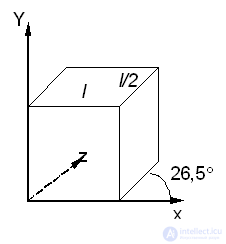
Fig. 3.12. Cabin Projection
The Cabinet projection (Fig. 3.12) has a projection direction that forms an angle with the projection plane = arctg(½) (≈26.5°). In this case, the segments perpendicular to the projection plane, after projection, are ½ of their actual length. Cabinet projections are more realistic than Cavalier projections, since the shortening with a coefficient of ½ is more consistent with our visual experience.
The central projection of any set of parallel lines that are not parallel to the projection plane will converge at a vanishing point. There are infinitely many vanishing points. If a set of lines is parallel to one of the principal coordinate axes, then their vanishing point is called a principal vanishing point. There are only three such points, corresponding to the intersections of the principal coordinate axes with the projection plane. Central projections are classified according to the number of principal vanishing points they have, and therefore the number of coordinate axes that intersect the projection plane.
1. One-point projection (Fig. 3.13).
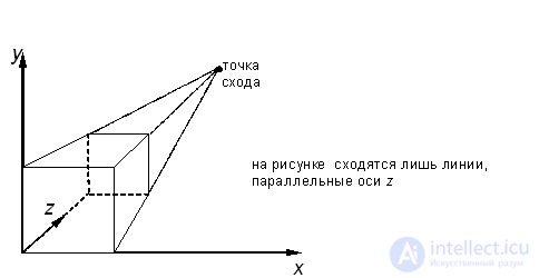
Fig. 3.13. One-point perspective
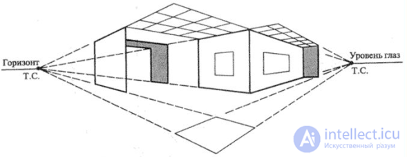
2. Two-point projection is widely used in architectural, engineering and industrial design.
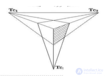
3. Three-point central projections are almost never used, firstly because they are difficult to construct, and secondly because they add little in terms of realism compared to a two-point projection.

Comments
To leave a comment
Video game architecture
Terms: Video game architecture