Lecture
Strip directional couplers are four-shoulder reciprocal devices (eight-port), designed for the directional selection of part of the microwave power from one (main) channel in other (additional - fig. 5.1). The directional transfer of energy in such devices is associated with the condition of full coordination of all its arms. With a perfect match, one shoulder ID of the additional channel is untied and the power does not enter it. In the other two shoulders called workers, input power distributed in accordance with the selected value of the connection between the channels. These properties allow the use of such devices for the construction of strip power dividers, mixers, modulators, discriminators, power adders, etc.
In addition, directional couplers can be used as independent nodes necessary for carrying out various kinds of measurements in the microwave range. It should be noted, however, that in real constructions of directional couplers the perfect matching is not achieved and. consequently, the theoretically untied shoulder partially receives power acting at its input.
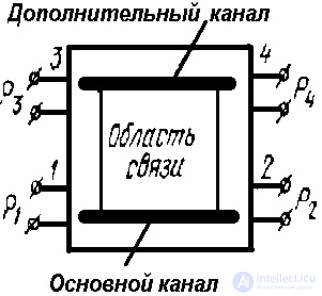
Picture 5.1 Functional diagram of the directional coupler
5.1. Key Features and Parameters
For specifications properties real directed taps (Fig. 5.1) use the following parameters.
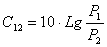
Operating attenuation, or power ratio at the input and output of the main channel, expressed in decibels:
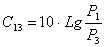
Transient attenuation (coupling), or the ratio of the power P 1 at the input of the main channel to the power P 3 existing at the output of the working arm of the additional channel (dB):
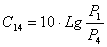
Decoupling or relationship power P 1 at the input of the main channel to the power P 4 of the additional channel existing at the output of the decoupled shoulder (dB):
Directivity, or power ratio at the output of the working and untied shoulder of the additional channel (dB):
The ratio of the power division, or power ratio at the output of the working arms of the main and additional channels (dB):
VSWR — standing wave ratio (parameter characterizing the degree of matching of the arms of the directional coupler with the loads). The value of VSWR from the side of any arm of the directional coupler is determined (measured) under the condition that all remaining arms are fully coordinated;
D f - working band of directional coupler, i.e. frequency section where communication unevenness (communication deviation from the mean value) or unevenness of the directivity value D C 34 does not exceed the specified value; f 0 —the average frequency of the working band of the coupler, equal to the arithmetic mean of the extreme frequencies f 1 and f 2 : f 0 = (f 1 + f 2 ) / 2;
l 0 - the central wavelength of the operating band of the coupler: l 0 = 2 l 1 l 2 / ( l 1 + l 2 ), where l 1 and l 2 is the longest and smallest wavelength within the working band D f .
To characterize the properties of directional couplers operating in the frequency band, it is also necessary to determine the frequency dependences of the above parameters C 13 , C 14 , C 34 , C 23 . When designing and creating directed otvetitel provide those or other parameters in most cases determined by the specific conditions of their use. So, when using couplers in single-ended mixers, the magnitude of transient attenuation C 13 is usually 15 ... 25 dB and is selected depending on the power of the local oscillator, the permissible response of the local oscillator circuit to the main channel, etc. When using the couplers in reflectometers and meters passing through For the purpose of reducing the measurement error, communication with the additional channel of the coupler is chosen to be even weaker: C 13 == 20 ... 30 dB.
As already noted, the directivity C 34 of real structures has a finite value, which is determined by the type of the coupler, the quality of matching shoulders with loads frequency range and is within 15 ... 40 dB. This option in all cases it is desirable to have as large as possible. For example, in taps intended for mixers, a decrease in the C 34 directionality leads to a decrease in isolation (C 14 = C 13 + C 34 ) and an increase in the penetration of the local oscillator power into the input circuit of the mixer. The latter circumstance, as is known, is highly undesirable. When designing directional couplers for broadband devices, it is necessary that the working band D f of the coupler should be wider than the device band, and the communication unevenness D C 13 and the irregularity of the D C 34 in the band should not exceed specified requirements, for example ± 0.3 dB. The broadband of the same coupler, as will be said below, is provided by the choice of the type of connection, the number of communication elements, the design and depends on the magnitude of the transitional attenuation and the given non-uniformity D C 13 .

Comments
To leave a comment
Microwave Devices and Antennas
Terms: Microwave Devices and Antennas