Lecture
Directional couplers form an extensive class of enlarged basic elements used both in the construction of extensive microwave paths and in various measuring devices. Recall that a directional coupler is called a reactive eight-port network, which has two pairs of ideally matched and mutually isolated inputs. Most of the directional couplers have a plane of symmetry and therefore the selection of the nominal values of their constituent elements and the analysis of the resulting scattering matrices can be performed by the method of symmetric and antisymmetric excitation
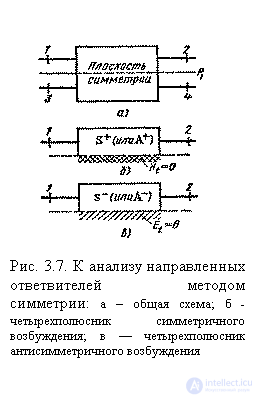
. We introduce the numbering of the inputs of the eight-port network shown in fig. 3.7, a. In accordance with formulas (2.74) and (2.75), the scattering matrix of the eight-port network in the presence of the plane of symmetry  should have the structure:
 ;
;  ;
; 
with the second order scattering matrix
 ;
; 
refer to the partial quadrupole symmetric and antisymmetric excitation, shown in Fig. 3.7,6 and Fig. 3.7, c. These two-port networks represent the upper halves of the eight-port network, cut off by the plane of symmetry with the boundary condition Ht = 0 (symmetric excitation, “+” index) or with the boundary condition  (antisymmetric excitation, the index "-"). The independent elements of the eight-port scattering matrix in Fig. 3.7, and are expressed as reflection coefficients as follows.
  and transfer ratios
  partial quadrupoles:
 ;
;  ;
;
 ;
;  ; (3.31)
 ;
; 
moreover, the reactivity of partial quadrupoles is equal  and
and  . The eight-port jet in fig. 3.7, and turns into a perfect directional coupler if the inputs are matched
  and at the same time achieved isolation of any two pairs of inputs. Depending on which inputs the decoupling is reached, the following types of direction are distinguished: 1) type 1 when decoupling pairs of inputs 1-3 and 2—4; 2) type II when decoupling pairs of inputs 1-4 and 2-3; 3) type III when decoupling pairs of inputs 1–2 and 3–4.

Consider successively each of the types of orientation.
Type 1 directivity. Joint compliance of the conditions of the coupler inputs  and once mated
  according to formulas (3.31) is equivalent to equalities
 ;
;  (3.32)
i.e., to achieve type 1 directivity, both partial quadrupoles of symmetric and antisymmetric excitation should be perfectly coordinated and differ only in the phases of transmission coefficients  and
and  . The phase difference of these transmission factors
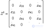
  called the differential phase shift for waves passing through the coordinated partial quadrupoles of symmetric and antisymmetric excitation. The ideal scattering matrix of a directional coupler of type 1, when conditions (3.32) are fulfilled, has the structure:
 ;
;  ;
;  (3.33)
Type 1 directional couplers belong to codirectional couplers, since the wave in the secondary transmission line 3-4 moves in the same direction as the wave exciting it in the primary line 1-2. In addition, type 1 directional couplers are quadrature, that is, the phase shift between elements  and
and  in the scattering matrix is equal to
  . In the directional coupler type 1, as a rule, there is a second plane of symmetry (at least electric), passing between pairs of inputs 1-3 and 2-4. Conditions (3.32) determining the type 1 directivity can be rewritten in terms of classical transfer matrices.
  for partial quadrupoles. C using the transition formulas between the matrices A and S from table. 3.1 we get the equations
  of which, given the materiality of the elements
  and
and  and imaginary elements
  and
and  in a reactive quadruple should be:
 type 1 directionality (3.34)
Differential phase shift is easily determined from the relation  resulting in the formula
 .
.
Expressions for nonzero elements of an ideal scattering matrix of a directional coupler of type 1 taking into account conditions (3.34) take the form
 (3.35)
where the top character refers to the element  and the bottom to the element
  .
.
2. Type II directivity. Joint fulfillment of junction conditions  and matching inputs
  in accordance with formulas (3.31) is possible only if equalities hold
  and
and  . Taking into account the canonical scattering matrix of a non-dissipative quadrupole (2.54), this leads to the expressions
 ;
;  ;
;  , (3.36)
Where  ,
,  ,
,  - independent real parameters that determine the scattering matrix of a reactive quadrupole.
The ideal scattering matrix of the directional type II coupler, when conditions (3.36) are fulfilled, takes the form:
 ;
;  ;
;  ; (3.37)

Type II directional taps refer to counter-directional taps, since the wave in the secondary transmission line 3-4 moves in the opposite direction with respect to the excitation wave in the primary transmission line 1-2. If the directional coupler of type II has a second plane of symmetry, passing between pairs of inlets 1-3 and 2-4, then  what means
  and
and  . Consequently, in the presence of two symmetry planes, the directional coupler of type II turns out to be quadrature. If the second plane of symmetry is not, but the selection of the parameters of the partial quadrupoles ensures equality
  , the type II directional coupler is obtained by a phase-in-phase coupler, i.e.
  .
.
Conditions  ,
,  Type II directivity, in terms of classical matrices, of the transfer of partial quadrupoles are as follows:
 ;
;

Hence, taking into account the materiality of the elements  and
and  and imaginary elements
  and
and  in reactive quadrupoles the conditions follow:
 type II directivity, (3.38)
taking into account which we obtain expressions for the calculation of the elements of the ideal scattering matrix (3.37):
 ;
;  (3.39)
3. Type III directionality. Joint fulfillment of junction conditions  and matching inputs
  in accordance with formulas (3.31) is possible only if equalities hold
 ;
;  (those.
  ).
). 
Taking into account the canonical scattering matrix of a reactive quadrupole, these conditions take the form:
 ;
;  ;
;  (3.40)
The ideal scattering matrix of the type III directional coupler, when conditions (3.40) are met, has the structure:

Conditions  and
and  , determining the direction of type III, in terms of classical transfer matrices of partial quadripoles give the equations

 ,
,
of which, by virtue of the materiality of the elements  and
and  and imaginary elements
  and
and  in a reactive quadrupole the conditions follow:
 type III directivity, (3.42)
and taking into account these conditions, we obtain the following expressions for the elements of the ideal scattering matrix (3.41):
 ;
;  . (3.43)

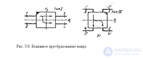
Type 1 directional couplers can be assigned to type III directional couplers if they have a second plane.
 |
geometric symmetry  (Fig. 3.8, a). Indeed, the rotation of the directional coupler type 1 in the plane of the pattern 90 ° clockwise and renumbering the inputs
  ,
,  ,
,  and
and  lead to a coupler with a scattering matrix of the form (3.41), i.e., to a directional type III coupler having a plane of symmetry
  . Therefore, in directional couplers with two planes of geometric symmetry, the adjustment of partial two-port networks of symmetric and antisymmetric excitation according to conditions (3.34) and (3.42) in some cases may be equivalent and lead to identical schemes of couplers (up to renumbering inputs).
Using the formulated conditions for matching and decoupling the inputs of directional couplers in terms of the parameters of partial quadrupoles, it is possible not only to easily understand the principle of operation of one or another coupler (of course, having a plane of symmetry), but also to get the relationships necessary for its design.
Comments
To leave a comment
Microwave Devices and Antennas
Terms: Microwave Devices and Antennas