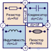
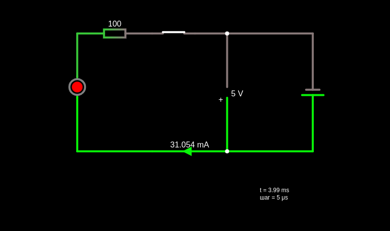
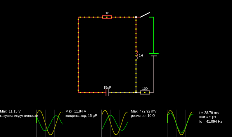
Shown here is a classic alternating-current circuit with passive elements connected in series
This page is a utility for simulating alternating current (ac) online with specified initial values.
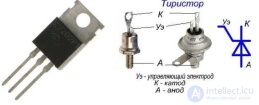
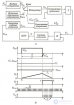
This is a simple single-diode AC rectifier circuit (a half-wave rectifier).
AC voltage source (on the left)
Frequency: 131 Hz
Amplitude: about ±6 V
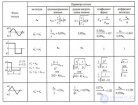
The signal is sinusoidal (an up-and-down wave)
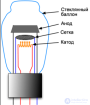
Light source (red LED)(in the center)
Passes current in only one direction
35 Ω resistor (the load)
Current flows through it
The output voltage is taken across it
Output (on the right)
This is the voltage across the resistor
The diode opens (passes current)
Current flows through the resistor to ground
A voltage appears at the output (the green "hump")
The diode closes
No current flows
The output voltage = 0
On the left (input) — an ordinary sine wave
On the right (output) — only the upper halves of the sine wave
This is exactly half-wave rectification
Because:
The diode "eats up" ~0.7 V (the voltage drop)
And some energy is lost
Input: a sine wave with amplitude
There is a diode (voltage drop of about 0.7 V)
Load: a resistor (it has almost no effect on the waveform)
Accounting for the diode drop
When the diode is open:
Where:
Then the maximum value:
The circuit does the following:
It converts alternating current into pulsating direct current, passing only the positive part of the signal.


Comments