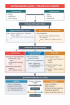
This is a NOR / OR gate that uses emitter-coupled logic, a high-speed logic that uses transistors. The two inputs are shown on the left. If either of them is high (-700 mV), then the OR output is high and the NOR output is low. If they are both low (-1.4 V), then the OR output is low and the NOR output is high. The base voltage of Q3 is fixed at a level where the base current is sufficient for Q3 to conduct current. This lowers Q3's collector level to about 740 mV, which lowers the OR output (through the follower connected to Q3's collector). Q3's emitter is high enough relative to the base of Q2 that Q2 cannot conduct, so Q2's collector stays at ground. This keeps the NOR output high (through a follower). If either of the two inputs is high, then the corresponding transistor conducts. This brings the collector of Q1 / Q2 low, which brings the NOR output low. It also raises the emitter of Q1 / Q2 high enough that Q3 cannot conduct, which brings the OR output high. The advantage of ECL is speed, because the transistors are never in saturation. They are either in cutoff or in the forward-active mode; the transistors can switch quickly between these two states. The disadvantage is that there is always a large current, and therefore high power consumption.
This page is a utility for simulating ecl nor / or online with specified initial values.


Comments