
A signalised crossroads on a single ATmega328P: 4 traffic lights — two vehicle heads (red/yellow/green) for two perpendicular directions and two pedestrian heads (red/green). While one direction goes on green, the perpendicular one stays red; pedestrians walk together with the vehicle flow parallel to them. The cycle includes a red+yellow phase and a common all-red gap for safety.
This page is a utility for simulating crossroads with 4 traffic lights on atmega328p — 2 vehicle and 2 pedestrian heads, perpendicular flows online with specified initial values.
This circuit models a signalised crossroads of two perpendicular roads on a single ATmega328P microcontroller. Instead of a single traffic light, four heads work here: two vehicle lights (one per direction) and two pedestrian lights. One pair serves one direction, the other pair serves the perpendicular direction.
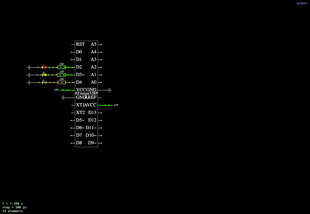
Microcontroller pin assignment:
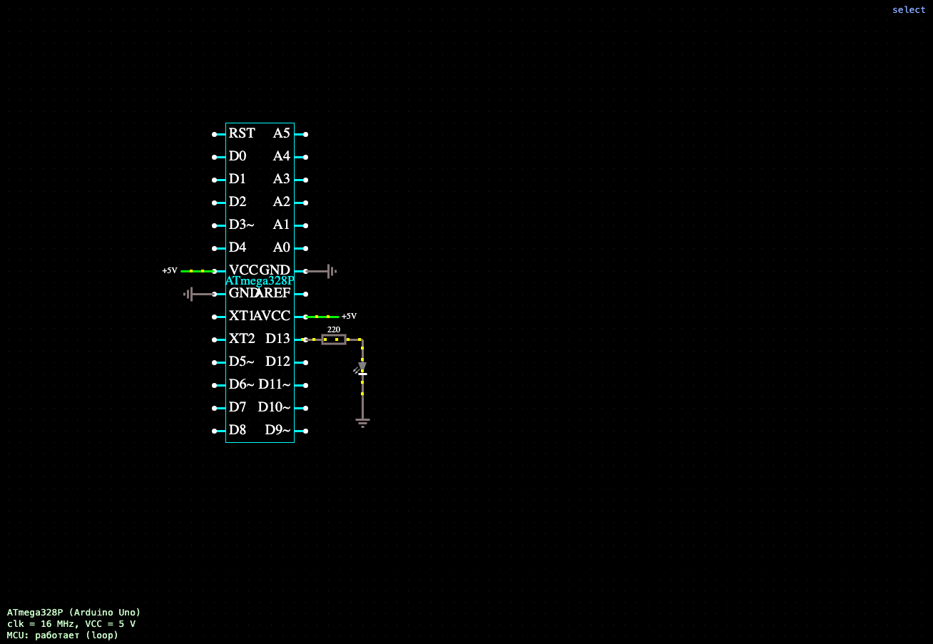
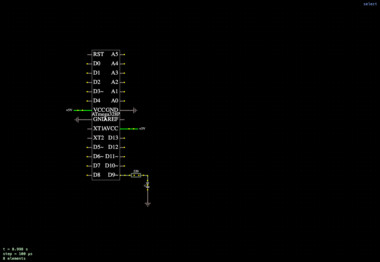
Each of the ten LEDs is connected to its pin through a current-limiting resistor to ground, setting a safe operating current and protecting the microcontroller pins.
In setup() all ten lines are configured as digital outputs. The intersection logic lives in loop() and is built around the main safety rule: the green signals of the two perpendicular directions are never on at the same time. A pedestrian crossing gets its "walk" green only while the parallel vehicle flow is green, and it turns red in advance — before that flow switches to yellow.
The full cycle (about 10.8 s) runs through these phases:
Phase durations are set by the constants GREEN_MS, YELLOW_MS, PREP_MS and ALLRED_MS and are timed with the delay() function. By editing them directly in the microcontroller properties inside the simulation environment, you can tune the green duration, the length of the pedestrian phase and the size of the safety gap, watching the intersection respond in real time.




Comments