
PWM example on ATmega328P (Arduino): analogWrite() smoothly ramps the LED brightness on pin D9 (fade in / fade out).
This page is a utility for simulating atmega328p pwm led fade circuit online with specified initial values.
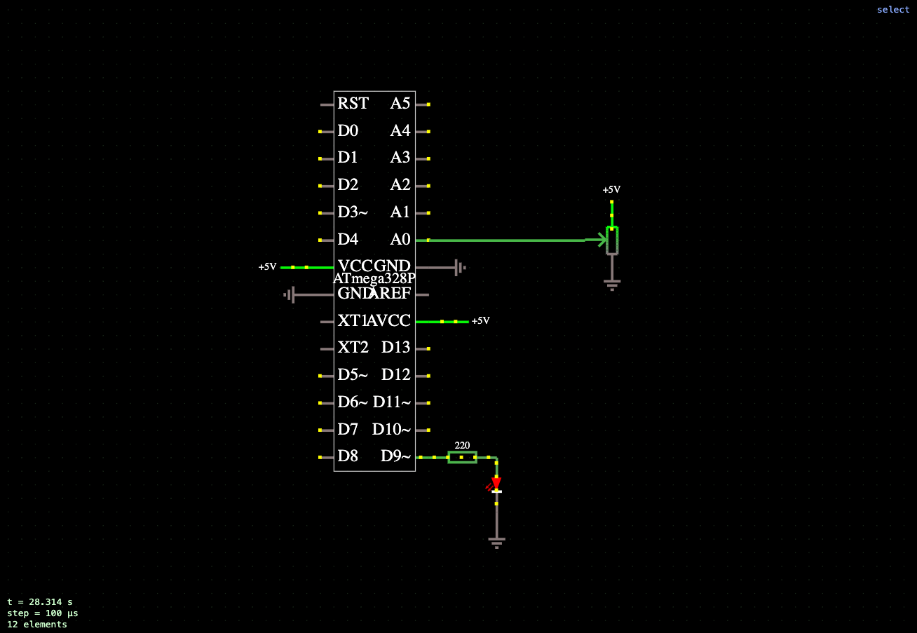
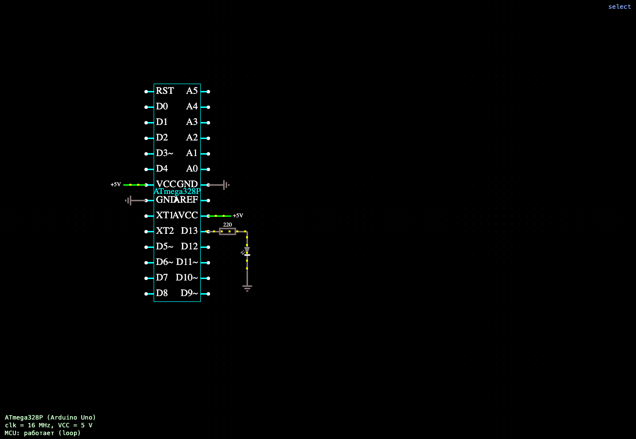
In this example, the ATmega328P microcontroller demonstrates the operation of pulse-width modulation (PWM). An LED is connected to digital pin D9, which supports hardware PWM signal generation. To limit current, the LED is connected through a 220 ohm current-limiting resistor.
After running the program in the setup() function, pin D9 is configured as an output. The main algorithm is implemented in the loop() function, which continuously changes the duty cycle of the PWM signal using the analogWrite() function. The value passed to analogWrite() ranges from 0 to 255, where 0 corresponds to the LED being completely off and 255 to maximum brightness.
First, the program gradually increases the PWM value, causing the LED to light up smoothly. After reaching maximum brightness, the duty cycle begins to decrease, ensuring a smooth dimming of the LED. Small delays between brightness changes create a visually continuous effect of changing the intensity of the light.
Using hardware PWM allows you to adjust the average voltage across the load without changing the supply voltage. Due to the high switching frequency, the human eye perceives the change in duty cycle as a smooth change in LED brightness.
The program source code, containing the standard setup() and loop() functions, can be edited directly in the microcontroller properties in the simulation environment. After making changes, the sketch is automatically compiled and uploaded to the ATmega328P model, allowing you to quickly modify the brightness control algorithm, experiment with duty cycle steps, fade-in and fade-out speeds, and explore the principles of pulse-width modulation in Arduino microcontrollers.



Comments