
A potentiometer on analog input A0 sets the LED brightness on D9: analogRead() reads the wiper (0..1023), analogWrite() outputs a proportional PWM duty. Drag the wiper with the mouse.
This page is a utility for simulating atmega328p potentiometer-controlled led brightness (adc to pwm) online with specified initial values.
Controlling LED brightness with a potentiometer on an ATmega328P (Arduino Uno board).
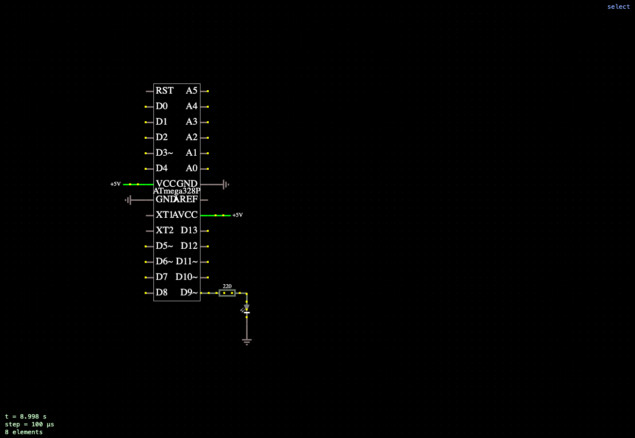
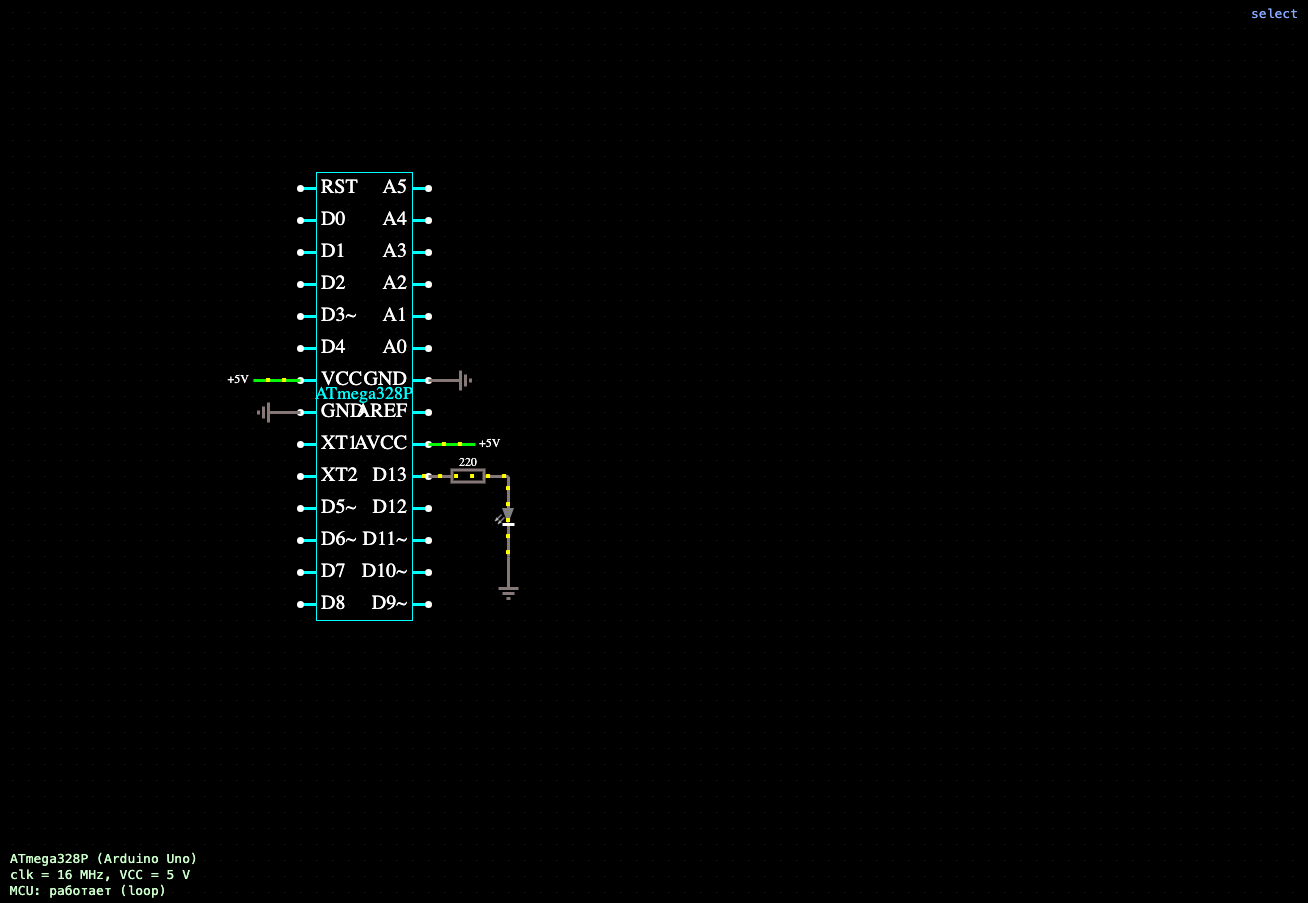
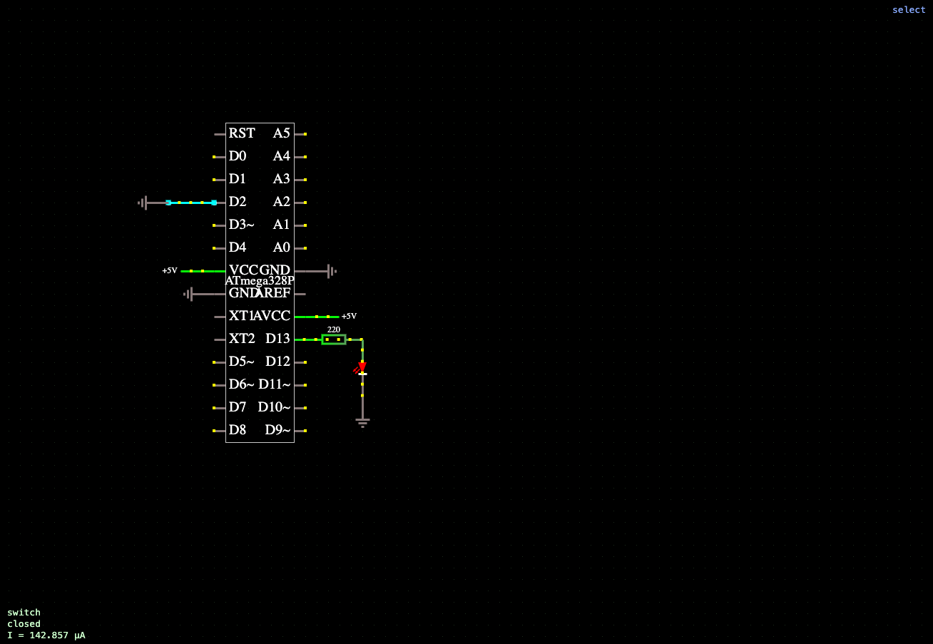
In this example, the ATmega328P microcontroller demonstrates how to work with analog inputs and pulse-width modulation (PWM). The potentiometer is connected to analog input A0 and used as an analog control signal source. The LED is connected to digital pin D9, which supports hardware PWM, through a 220 ohm current-limiting resistor.
After running the program, the setup() function configures pin D9 as an output. In the loop() function, the microcontroller continuously reads the potentiometer wiper position using the analogRead(A0) function. The analog-to-digital converter (ADC) converts the voltage at input A0 to a digital value in the range of 0 to 1023, which corresponds to the current position of the potentiometer wiper.
The resulting value is scaled to a range from 0 to 255 and passed to the analogWrite(D9, ...) function, which generates a PWM signal with the corresponding duty cycle. As a result, the LED brightness changes proportionally to the potentiometer position: at the minimum position, the LED is barely illuminated, while at the maximum position, it reaches full brightness. Intermediate positions provide a smooth change in brightness.
During the simulation, the potentiometer position can be changed by dragging the mouse, allowing you to observe the voltage change at the analog input and the corresponding change in LED brightness in real time. This example clearly demonstrates the principles of analog-to-digital conversion, analog signal processing, and load control using pulse-width modulation.
The program source code, containing the standard setup() and loop() functions, can be edited directly in the microcontroller properties. After making changes, the sketch is automatically compiled and loaded into the ATmega328P model, allowing you to experiment with analog data processing algorithms, change the signal update rate, and study the interaction of analog inputs with the microcontroller's PWM outputs.






Comments