
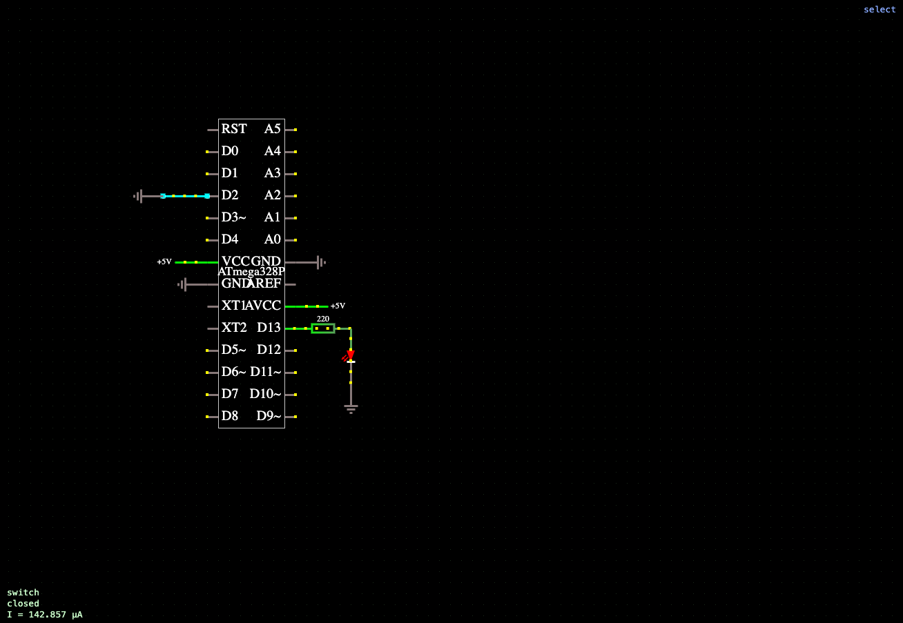
Example of an ATmega328P microcontroller (Arduino Uno): the built-in Blink firmware toggles an LED on pin D13. The LED is connected to D13 through a 220 Ohm current-limiting resistor. The setup()/loop() sketch can be edited in the chip properties.
This page is a utility for simulating atmega328p (arduino) led blink circuit online with specified initial values.
After running the simulation, the microcontroller runs the built-in Blink demo firmware, which periodically changes the logic level on digital pin D13. An LED is connected to this pin via a 220 ohm current-limiting resistor, causing the LED to alternately turn on and off at intervals of approximately one second, clearly demonstrating the microcontroller's program execution.
The program source code consists of the standard setup() and loop() functions. The setup() function is executed once after power-up or a device reset and is used for initial peripheral configuration (for example, setting pin D13 to output mode). The loop() function then executes continuously in an infinite loop, periodically turning the LED on and off using pin control and delay commands.
In the simulation environment, the sketch text can be edited directly in the microcontroller properties, without using the external Arduino IDE. After making changes, the program is automatically compiled and uploaded to the microcontroller model, allowing you to immediately observe the results and experiment with the control algorithm without modifying the circuit. This example demonstrates the basic principles of microcontroller programming: setting up input/output ports, managing digital signals, and organizing a continuous program execution cycle.


Comments