Lecture
1. Features of computer networks.
1.1. Seven-level OSI model
Currently, computer systems are widely used in telecommunications. Most devices, including subscriber terminals, are computer systems, and the provision of telecommunication services is primarily the exchange of data between computers.
Transferring data between two computers is a complex task. It is necessary to coordinate the mechanical and electrical parameters of the cables and connectors used, the voltage levels, the format of the transmitted data, error handling methods and many other parameters.
To solve a complex task, the principle of multilevel decomposition is often used, according to which the task is divided into a number of simpler subtasks, for solving each of which a separate module is defined (Fig. 1.1.).
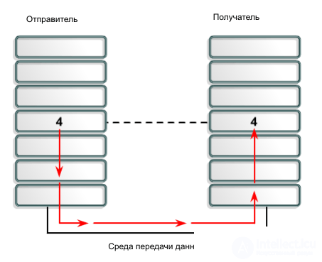 |
Fig.1.1. |
All modules are divided into hierarchical levels. The higher module can refer to the lower one, the results of the module are transferred to the module of the higher level.
Data exchange between two modules located on the same level in different nodes can be considered as direct data exchange between these modules. Data exchange between modules lying on the same level is performed in accordance with a specific protocol. A hierarchically organized set of protocols sufficient for interworking is called a protocol stack. As a rule, protocols operate on data blocks, which are collectively called PDUs (Protocol Data Unit). To exchange data between two computers, it is necessary that they support the same protocol stack.
A protocol (protocol stack) is primarily a standard (set of standards) according to which data is exchanged. Software (hardware) modules that communicate in accordance with this standard represent the software (hardware) implementation of the protocol stack. Often, the implementation of a particular protocol stack is also called a protocol stack.
Different implementations of the same protocol stack may vary depending on the manufacturer, operating system, and other factors. For example, the implementation of the TCP / IP stack under Windows differs from the TCP / IP implementation under UNIX in terms of the capabilities provided to the application process. But since in both cases the TCP / IP stack is implemented in accordance with the standard, data exchange between UNIX and Windows machines supporting TCP / IP is ensured.
Some protocols are proprietary (eng. Property) , i.e. is the property of the developer and may not be supported by hardware or software from other manufacturers. In order to avoid compatibility problems, it is recommended to focus on open protocols , which are an international standard, for which most manufacturers orient themselves to mandatory support.
There are protocols with connection establishment (connection-oriented) and connectionless (connectionless) . Connection-based protocols establish a connection between the sender and receiver before sending data. Typically, this is a virtual (or logical) connection - a virtual circuit. The devices organizing the connection will agree on the parameters that must be provided during data transfer, for example, the route and the minimum guaranteed transmission rate. Switching physical channels when establishing a virtual connection does not occur.
Connectionless protocols are also called datagram protocols. When sending a data block, the recipient is not notified in any way, and the lost PDUs are not sent again. Such protocols work in the best effort mode, i.e. they are trying to transfer data as best and losslessly as possible, but reliability is not guaranteed.
The multi-level approach ensures the independence of the internal structure of individual modules, provided that the intermodule interface remains unchanged. For example, when replacing a network card, it is enough to install a new network card driver, while in applications and software implementing higher-level protocols, no changes need to be made.
The seven-tier OSI model was developed by ISO in the early 80s by a number of international standards organizations (ITU, ISO, etc.). Later, a software implementation of the OSI protocol stack was created, which fully corresponds to this model. But by that time, the TCP / IP stack, which is much simpler and cheaper than the OSI stack, was already widely used; therefore, the OSI stack could not be implemented. However, the OSI model is of substantial theoretical interest and is used to describe interworking. The terminology of the OSI model is used everywhere.
The OSI model contains seven levels (Fig. 1.2): 1 - physical (physical), 2 - channel (datalink), 3 - network (network), 4 - transport (transport), 5 - session (session), 6 - presentation level (presentation), 7 - application.
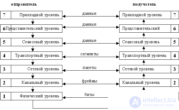 |
Fig.1.2. |
The application layer provides applications with access to the network. The application layer communicates with the representative layer.
The representative layer provides coordination and transformation of the formats of transmitted data between modules of the application layer. At the representative level, encryption / decryption, compression / decompression, or other transformation of the transmitted data can be performed.
As an example of the functions of the representation level, you can give the definition of encoding a web page by the browser. Often, when loading a web page, it is displayed in unreadable characters due to incorrect encoding definition, which is an example of a representation level failure.
The session layer provides dialogue management tools that allow you to record which of the interacting parties is currently active, and also provides synchronization tools as part of the messaging procedure. An example of the session-level function is the definition of the active side in half-duplex voice communication.
The transport layer provides data transfer between two applications with the required level of reliability.
At the transport level, the data stream is split into segments when sending data, or the source data stream is assembled from segments at reception. A segment is a transport data unit (PDU).
In the case of transmission of data that is critical to errors (for example, transfer of binary files), reliable transmission with error correction and retransmission of lost segments is needed. In this case, reliable protocols with the establishment of virtual connections are used. When transmitting some types of traffic that are sensitive to latency, but allow for partial loss of the transmitted data (for example, streaming video), datagram protocols can be used.
The network layer provides packet delivery between two nodes in a network with an arbitrary topology. A packet is called a network layer data block. The generalized format of the package is depicted in Figure 1.1.
 |
Fig.1.3. |
The main task of the network layer is to search for a route from one computer to another and transmit a packet along this route. Reliability of data transmission, as a rule, is provided by higher-level protocols. A package generally consists of a header and a data field. The data field most often contains a segment of the transport layer, and the header contains service information, as well as the addresses of the sender and recipient.
At the network level, the addressing of computers is introduced. Network layer addresses are called logical addresses, since addressing is independent of hardware. The network layer addressing is hierarchical, the address consists of at least two parts - the network number and the node number on this network. At the same time, the network is primarily a logical concept; to a single network are those computers whose network number is the same.
Data transfer between networks is carried out with the help of special devices called routers. The router is a special-purpose computer that has several network interfaces, with each interface being part of the network to which it is connected (Fig. 1.4).
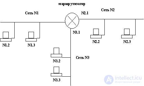 |
Fig.1.4. |
The task of the router is determining the route and packet switching, i.e. the router must accept the packet on one of its interfaces, determine which interface this packet should be forwarded on, and send the packet through this interface. The task of choosing a route is called routing.
The protocols related to the network layer can be divided into 2 groups - routed protocols (routing protocols) and routing protocols (routing protocols). Routing protocols are used to transfer data between hosts, whereas routing protocols are used to transfer routing information between routers.
The link layer ensures the transmission of a data frame between any nodes in networks with a typical topology or between two neighboring nodes in networks with an arbitrary topology. Also at the data link layer, access to the data transfer medium is controlled.
A frame (English frame - frame) or less often a frame is called a link level PDU. A frame is encapsulated in a frame's data field. The link layer uses flat or non-hierarchical addressing. Link-level addresses in local networks are often called MAC addresses, or physical addresses.
Link layer addressing and frame format depend on the type of equipment. This means that the sender and the receiver must use the same standard on the data link layer for frame transmission. For example, you can combine two computers with Etehrnet network cards in the same network segment, but combining computers with Ethernet and Token ring network cards in one segment is impossible.
Generally, the frame format is presented in Figure 1.5.
 |
Fig.1.5. |
A frame consists of a header, a data field, and a trailer. The header contains the service information as well as the address information required to deliver the frame. The data field contains a network-level data block, i.e. package. The trailer contains a checksum to determine if the frame was corrupted during transmission.
In order to avoid a single node capturing the data transmission medium, the maximum frame size is limited, and the maximum size of the data field is correspondingly limited. The maximum size of the frame data field is called the MTU - Maximum Transfer Unit. For example, for Ethernet networks, the MTU is 1500 bytes.
Physical level
The task of the physical layer is to transmit individual bits over physical channels, such as twisted pair or fiber-optic cable. At this level, the characteristics of the data transmission medium, the parameters of electrical signals, standards for cabling, modulation / demodulation, coding, etc. are defined. or packages.
Encapsulation order.
When transferring data from the sender to the recipient (Fig.1.11), the data first arrive at the application level, from the application to the representative, from the representative to the session, and then to the transport level. At the transport level, the data stream is broken up into segments. At the network layer, the segment is encapsulated into a packet, at the channel level the packet is encapsulated into a frame, and the frame at the physical layer is transmitted bit by bit through the data transfer medium. The recipient performs the reverse process, i.e. a packet is extracted from the frame, a segment is extracted from the packet. At the transport level, the initial data flow is collected from the segments, after which the data is transmitted to the session level, then to the representative one, from the representative one to the application level. The application layer transfers data to the receiving application.
Thus, the following encapsulation order takes place: segment-packet-frame (Fig. 1.1.12).
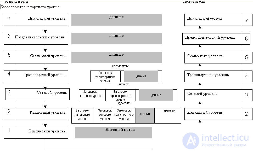
Fig.1.6.
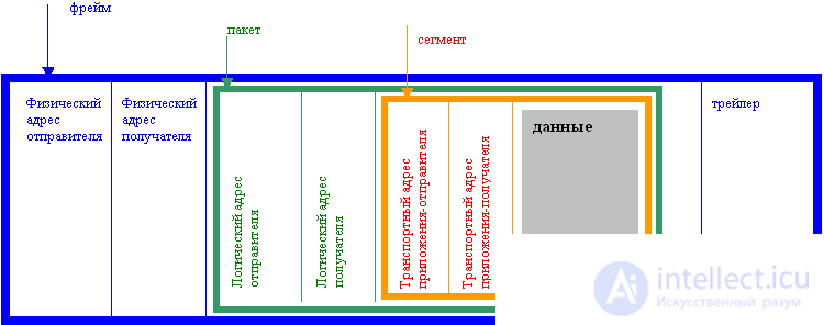 |
Fig.1.7. |
1.2. Computer Network Classification
The most commonly used classification of networks according to their length. If the distance between the two most distant nodes does not exceed 1 km, the network is considered a local area network, abbreviated LAN (Local Area Network - LAN). Short distances in local networks allow the use of channels with a large bandwidth at relatively low costs. Currently, data transfer at speeds up to 10 Gbit / s is provided in LAN. Most often the LAN serves one building or group of buildings.
A network longer than 100 km is considered a global network (World Area Network - WAN). The nodes of global networks are geographically dispersed, making it difficult to lay fast lines of communication between them. Therefore, the data transfer rate for the end user in global networks is significantly lower.
Network length from 1 to 100 km called the city network (Metropolitan Area Network - MAN). This type of network appeared relatively recently with the development of cable infrastructure in large cities. The data transfer rate in such networks is comparable to the data transfer rate in the LAN.
Currently, there is a gradual convergence of local and global networks. Thanks to the introduction of fiber-optic communication lines and new methods of data transmission, the speed of backbone channels of global networks is increasing. Broadband access is increasingly being used to tackle the last mile problem. Through the use of broadband access, millions of users can connect to the Internet at speeds that were previously only available on a LAN.
Convergence of networks.
The idea of convergence is to gradually merge computing and telecommunication networks. At present, packet-switched networks are used not only for transmitting computer data, but also for transmitting voice and video traffic, mobile communications, television programs, and radio programs. Also merging the functionality of computing and communication devices. Using a mobile phone, you can access the Internet, and you can make phone calls using a computer. This approach will allow the user to access all services from anywhere, from any device, at any time. In this case, fundamentally new services can be introduced, for example, video on demand.
The problem of quality of service (Quality of Service - QoS).
Initially, computer networks were supposed to be used to transmit computer traffic of a pulsed nature. For example, a file is loaded as fast as possible, while changing the download time within a few seconds is usually not critical. At the same time, the loss of at least one segment of the transmitted data is unacceptable, as this may lead to file corruption.
Multimedia traffic is different. When transmitting multimedia traffic (for example, voice), it is necessary to transmit data in small parts, but with a fixed interval. Partial loss of transmitted information is allowed, but traffic is sensitive to delay, as well as to a change in the delay time (jitter). The mechanisms for distinguishing between different types of traffic and ensuring the required quality of services are discussed in Section 8.
1.3. Calculus systems.
Binary system of calculation - positional system of calculation on the basis of 2, 0 and 1 are used as numbers. When working with IP networks, in most cases it is enough to be able to work with 8-bit numbers.
An example of converting from binary to decimal:
10111001
No discharge | 7 | 6 | five | four | 3 | 2 | one | 0 |
2 n | 128 | 64 | 32 | sixteen | eight | four | 2 | one |
numeral | one | 0 | one | one | one | 0 | 0 | one |
10111001 2 = 1 × 2 7 + 0 × 2 6 + 1 × 2 5 + 1 × 2 4 + 1 × 2 3 + 0 × 2 2 + 0 × 2 1 + 1 * 2 0 = 128 + 32 + 16 + 8 + 1 = 185
To convert from decimal to binary, you can use the division method with the remainder. Let's convert the number 161 to binary form.
No discharge | Division operation | Result | Remainder | Value of discharge |
0 | 161/2 | 80 | one | <1 |
one | 80/2 | 40 | 0 | <0 |
2 | 40/2 | 20 | 0 | <0 |
3 | 20/2 | ten | 0 | <0 |
four | 10/2 | five | 0 | <0 |
five | 5/2 | 2 | one | <1 |
6 | 2/2 | one | 0 | <0 |
7 | 1/1 | 0 | one | <1 |
Thus, 168 10 = 10100001 2
To convert numbers from 1 to 255, you can use a simplified algorithm.
For example, convert the number 161 to binary:
128 <168. in the 7th digit <1 161 - 128 = 33.
64> 33. in the 6th digit <0
32 <33. in the 5th digit <1 33 - 32 = 1.
16> 1. in the 4th digit <0
8> 1. in 3 digit <0
4> 1. in 2 digit <0
2> 1. in 1 digit <0
1 = 1. 0 bit <1
Thus, 168 10 = 10100001 2
The hexadecimal system is the positional calculus on the base 16. It is convenient that only two digits are required to write one byte. The hexadecimal numbering system uses numbers from 0 to 9 as well as Latin letters from A to F. A = 10, B = 11, C = 12, D = 13, E = 14, F = 15.
When writing hexadecimal numbers, often “ 0 x ” is written before the number, for example, 0xAF1.
Conversion of hexadecimal numbers to decimal is carried out similarly to the conversion of binary numbers to decimal. For example,
0xAF1 = A × 16 2 + F × 16 1 + 1 × 16 0 = 10 × 256 + 15 × 16 + 1 × 1 = 2560 + 240 + 1 = 2801
To convert decimal numbers to hexadecimal numbers, you can use division with remainder. For example, let's convert 2801 10 to hexadecimal form:
No discharge | Division operation | Result | Remainder | Value of discharge |
0 | 2801/16 | 175 | one | <1 |
one | 175/16 | ten | 15 | F < |
2 | 10/16 | ten | 0 | <A |
You can also use the algorithm shown in Figure 8 for hexadecimal numbers. For example, convert 242 to hex.
242 <15 × 16 1 in 1 digit F 242 - 15 × 16 1 = 242 - 240 = 2
2 = 2 in 2 digit <2 <
Thus, 242 10 = 0xF2
Преобразование из двоичной формы в шестнадцатиричную осуществляется следующим образом: двоичное число разбивается на группы по 4 бита справа налево, при этом каждая группа отдельно преобразуется в шестнадцатиричную форму. При необходимости двоичное число можно дополнить нулями слева. For example:
Исходное число | 1101011101110101101 = 01101011101110101101 | ||||
Результат разбиения | 0110 | 1011 | 1011 | 1010 | 1101 |
Десятичный эквивалент | 6 | eleven | eleven | ten | 13 |
Шестнадцатиричные цифры | 6 | B | B | A | D |
Result | 0x6BBAD | ||||
Преобразование из шестнадцатиричной формы в двоичную осуществляется аналогично: каждая цифра шестнадцатиирчного числа преобразуется в двоичную форму и записывается в 4-х битах, при необходимости используется дополнение нулями слева. For example,
Исходное число | 0xF12A3 | ||||
Шестнадцатиричные цифры | F | one | 2 | A | 3 |
Десятичный эквивалент | 15 | one | 2 | ten | 3 |
Двоичный эквивалент | 1111 | 0001 | 0010 | 1010 | 0011 |
Result | 11110001001010100011 | ||||
Comments
To leave a comment
Computer networks
Terms: Computer networks