
Lecture
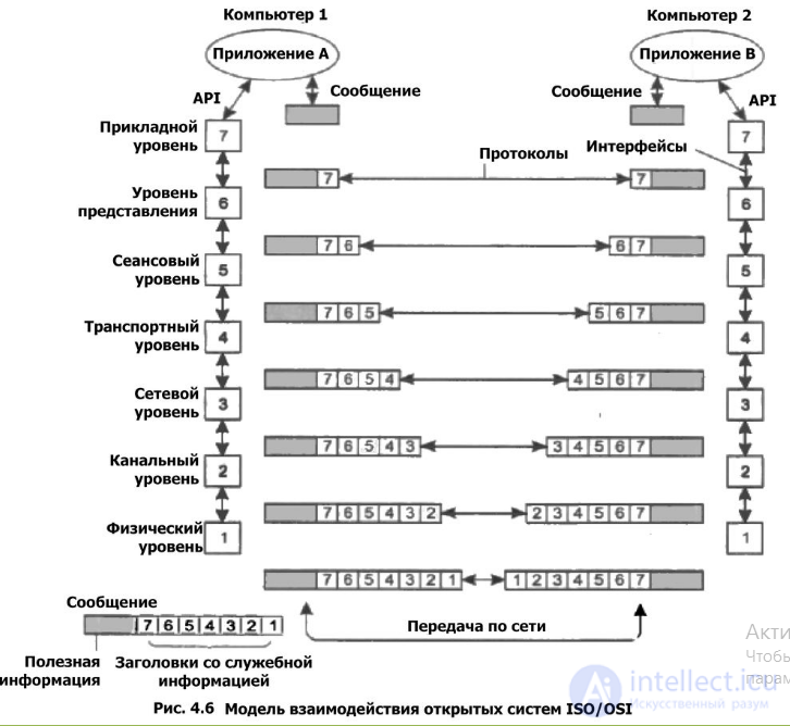
To organize the interaction of devices on a network, the International Organization for Standardization, or simply ISO, approved a model describing how computers are joined into a network.
The model is called OSI (Open Systems Interconnection).
The OSI model is built on seven hierarchically arranged layers, across which all the functions required for transmitting information are distributed. The number seven was not chosen by chance: fewer layers offered no particular advantages, while more than seven layers, because of vertical overhead, led to unnecessary consumption of system resources.
When the ISO/OSI standard was being developed, no thought was given to the concept of real time, and the rise of fieldbuses was not foreseen. Despite this, it was later accepted that the OSI model is quite suitable for describing the operation of industrial field-level networks as well.
The lowest layer of the OSI model, the physical layer, is the transmitting one; it describes the mechanical and physical parameters needed for data transmission. The next one, the data link layer, manages the interaction of networks at the physical level and controls the occurrence of errors. Routing is built at the network layer, or in other words, the path is selected. For example, in a telephone network, the route is chosen at the network layer depending on the dialed phone number, which ensures correct switching of subscribers. The transport layer manages the flow of information and ensures the correct order of data packets. The next one, the fifth, the session layer, serves to organize simultaneous data exchange between different parties. At this layer the participants in a session are identified, and if a session is interrupted, it is resynchronized. The presentation layer, as it is also called, agrees on the language of the symbols transmitted in data packets and is also responsible for encrypting and decrypting information. Finally, the seventh, application layer can be called an interface to the outside world. It provides a set of user communication services. You should be well familiar with application-layer protocols, for example HTTP, FTP, POP3, SMTP, and many others.
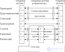
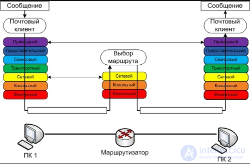
It is also appropriate here to mention the differences between such concepts as an interface and a data transmission protocol.
The OSI network model (The Open Systems Interconnection model) is the network model of the OSI/ISO network protocol stack. Through this model, different network devices can interact with one another. The model defines the different layers of interaction between systems. Each layer performs specific functions in this interaction.
The OSI model was developed in the late 1970s to support the diverse computer networking methods that were competing at the time for use in large national networking efforts in France, the United Kingdom, and the United States. In the 1980s it became a working product of the Open Systems Interconnection group of the International Organization for Standardization (ISO). The model failed to give a complete description of networking and did not win the support of architects in the early days of the Internet, which was subsequently reflected in the less prescriptive TCP/IP, largely under the direction of the Internet Engineering Task Force
In the early and mid-1970s, networking was mostly either sponsored by governments (the NPL network in the UK, ARPANET in the US, CYCLADES in France) or developed by vendors using proprietary standards, such as IBM Systems Network Architecture and Digital Equipment Corporation DECnet. Public data networks were only beginning to appear, and they used the X.25 standard in the late 1970s.
An experimental packet-switching system in the UK around 1973–1975 revealed the need to define higher-level protocols. The British National Computing Centre publication "Why Distributed Computing", which resulted from extensive research into the future configurations of computer systems, led the UK to present arguments for the creation of an international standards committee to cover this area at an ISO meeting in Sydney in March 1977.
Starting in 1977, the International Organization for Standardization (ISO) ran a program to develop general standards and methods of networking. A similar process was under way in the International Telegraph and Telephone Consultative Committee (CCITT). Both bodies developed documents defining similar network models. The OSI model was first defined in its initial form in Washington, D.C., in February 1978 by Hubert Zimmermann of France, and the draft standard was published by ISO in 1980.
The developers of the model had to deal with competing priorities and interests. The pace of technological change made it necessary to define standards to which new systems could converge, rather than standardizing procedures after the fact; this is the reverse of the traditional approach to standards development . Although it was not a standard itself, it provided a framework within which future standards could be defined.
In 1983, the CCITT and ISO documents were merged to form the Basic Reference Model for Open Systems Interconnection, usually called the OSI Reference Model or simply the OSI model. It was published in 1984 by ISO as standard ISO 7498 and by the renamed CCITT (now called the Telecommunication Standardization Sector of the International Telecommunication Union, or ITU-T) as standard X.200.
OSI consisted of two main components: an abstract model of networking, called the Basic Reference Model or seven-layer model, and a set of network protocols. OSI is a major achievement in teaching networking concepts. It promotes the idea of a consistent model of protocol layers, defining the interaction between network devices and software.
The concept of the seven-layer model was developed by Charles Bachman at Honeywell Information Systems. Various aspects of OSI design evolved from experience with the NPL network, ARPANET, CYCLADES, EIN, and the International Networking Working Group (IFIP WG6.1). In this model, a network system was divided into layers. Within each layer, one or more entities implement its functionality. Each entity interacted directly only with the layer immediately below it and provided facilities for use by the layer above it.
OSI standards documents are available from the ITU-T as the X.200-series recommendations. Some protocol specifications were also available as part of the ITU-T X series. The equivalent ISO and ISO/IEC standards for the OSI model were available from ISO. Not all of them are free.
OSI was an industry initiative aimed at getting industry participants to agree on common network standards to provide multi-vendor interoperability. It was common for large networks to support multiple sets of network protocols, with many devices unable to interoperate with other devices because of a lack of common protocols. In the late 1980s and early 1990s, engineers, organizations, and countries were divided over which standard, the OSI model or the Internet protocol suite, would lead to the best and most robust computer networks. However, while OSI was developing its networking standards in the late 1980s, TCP/IP came into widespread use on multi-vendor networks for internetworking.
The OSI model is still used as a reference for teaching and documentation[10]; however, the OSI protocols originally conceived for this model did not become popular. Some engineers argue that the OSI reference model is still relevant to cloud computing. Others believe that the original OSI model does not correspond to modern networking protocols and propose a simplified approach instead.[11]
Communication protocols allow an entity on one host to interact with the corresponding entity at the same layer on another host.
At each layer N, two entities exchange protocol data units (PDUs) using that layer's protocol on the corresponding devices. Each PDU contains a service data unit (SDU) associated with the protocol above or below.
Data processing by two communicating OSI-compliant devices proceeds as follows:
The OSI model, which was defined in the ISO/IEC 7498 standard, consists of the following parts:
ISO/IEC 7498-1 is also published as ITU-T Recommendation X.200.
| Model | |||||
|---|---|---|---|---|---|
| Layer | Data type (PDU[12]) | Functions | Examples | Equipment | |
| Host layers |
7. Application | Data | Access to network services | HTTP, FTP, POP3, WebSocket | Hosts
(network clients) |
| 6. Presentation | Data representation and encryption | ASCII, EBCDIC | |||
| 5. Session | Communication session management | RPC, PAP, L2TP | |||
| 4. Transport | Segments
(segment) /Datagrams (datagram) |
End-to-end connections and reliability | TCP, UDP, SCTP, PORTS | ||
| Media[13] layers |
3. Network | Packets (packet) | Path determination and logical addressing | IPv4, IPv6, IPsec, AppleTalk, ICMP | Router |
| 2. Data link | Bits (bit)/ Frames (frame) |
Physical addressing | PPP, IEEE 802.22, Ethernet, DSL, ARP, network card. | Switch,
access point |
|
| 1. Physical | Bits (bit) | Working with the transmission medium, signals, and binary data | USB, cable (twisted pair, coaxial, fiber-optic), radio channel | Hub,
Repeater (network equipment) |
In the literature, it is most common to begin describing the layers of the OSI model with layer 7, called the application layer, at which user applications access the network. The OSI model ends with layer 1, the physical layer, which defines the standards that independent manufacturers impose on data transmission media:
Any protocol of the OSI model must interact either with protocols of its own layer or with protocols one layer above and/or below its own. Interactions with protocols of its own layer are called horizontal, and those with layers one above or below are called vertical. Any protocol of the OSI model can perform only the functions of its own layer and cannot perform the functions of another layer, which is not the case in protocols of alternative models.
Each layer corresponds, with some degree of approximation, to its own operand: a logically indivisible data element that can be handled at that layer within the model and the protocols used. At the physical layer the smallest unit is the bit; at the data link layer, information is grouped into frames; at the network layer, into packets (datagrams); at the transport layer, into segments. Any piece of data logically grouped for transmission (a frame, packet, or datagram) is considered a message. In general, messages are the operands of the session, presentation, and application layers.
The physical and data link layers are considered the basic networking technologies.
The application layer is the top layer of the model, providing the interaction of user applications with the network:
Application-layer protocols: RDP, HTTP, SMTP, SNMP, POP3, FTP, XMPP, OSCAR, Modbus, SIP, TELNET, and others.
The definitions of an application-layer protocol and a presentation-layer protocol are very blurred, and whether a protocol such as HTTPS belongs to one layer or the other depends on the end service that the application provides.
If a protocol, for example HTTPS, is used to view a simple web page through a browser, it can be regarded as an application-layer protocol. But if HTTPS is used as a low-level protocol for transmitting financial information, for example via ISO 8583, then HTTPS will be a presentation-layer protocol, and ISO 8583 will be an application-layer protocol. The same applies to the other application-layer protocols listed in this article.
The presentation layer provides protocol conversion and data encoding/decoding. Application requests received from the application layer are converted at the presentation layer into a format for transmission over the network, and data received from the network is converted into the applications' format. At this layer, compression/decompression or encryption/decryption can be performed, as well as redirection of requests to another network resource if they cannot be handled locally.
The presentation layer is usually an intermediate protocol for converting information from the adjacent layers. This allows applications on heterogeneous computer systems to exchange data in a way that is transparent to the applications. The presentation layer provides formatting and code conversion. Code formatting is used to ensure that the application receives information for processing that makes sense to it. When necessary, this layer can translate from one data format to another.
The presentation layer deals not only with data formats and representation but also with the data structures used by programs. Thus, layer 6 provides the organization of data as it is sent.
To understand how this works, imagine two systems. One uses the Extended Binary Coded Decimal Interchange Code (EBCDIC) to represent data, for example an IBM mainframe, and the other uses the American Standard Code for Information Interchange (ASCII), which most other computer manufacturers use. If these two systems need to exchange information, a presentation layer is needed to perform the conversion and translate between the two different formats.
Another function performed at the presentation layer is data encryption, which is used when the transmitted information must be protected from access by unauthorized recipients. To accomplish this, the processes and code at the presentation layer must perform data transformation. This layer also contains other routines that compress text and convert graphic images into bit streams so that they can be transmitted over the network.
Presentation layer standards also define how graphic images are represented. The PICT format, an image format used to transfer QuickDraw graphics between programs, can be used for this purpose.
Another presentation format is the Tagged Image File Format (TIFF), which is typically used for high-resolution raster images. The next presentation layer standard that can be used for graphic images is the one developed by the Joint Photographic Experts Group; in everyday use this standard is simply called JPEG.
There is another group of presentation layer standards that defines the representation of sound and motion pictures. These include the Musical Instrument Digital Interface (MIDI) for the digital representation of music; the MPEG standard, developed by the Moving Picture Experts Group and used for compressing and encoding videos on compact discs, storing them in digitized form and transmitting them at speeds of up to 1.5 Mbit/s; and QuickTime, a standard describing audio and video elements for programs running on Macintosh and PowerPC computers.
Presentation layer protocols: AFP — Apple Filing Protocol, ICA — Independent Computing Architecture, LPP — Lightweight Presentation Protocol, NCP — NetWare Core Protocol, NDR — Network Data Representation, XDR — eXternal Data Representation, X.25 PAD — Packet Assembler/Disassembler Protocol.
The session layer of the model maintains the communication session, allowing applications to interact with each other over an extended period of time. The layer manages session creation and termination, information exchange, task synchronization, determination of the right to transmit data, and maintaining the session during periods of application inactivity.
Session layer protocols: ADSP (AppleTalk Data Stream Protocol), ASP (AppleTalk Session Protocol), H.245 (Call Control Protocol for Multimedia Communication), ISO-SP (OSI Session Layer Protocol (X.225, ISO 8327)), iSNS (Internet Storage Name Service), L2F (Layer 2 Forwarding Protocol), L2TP (Layer 2 Tunneling Protocol), NetBIOS (Network Basic Input Output System), PAP (Password Authentication Protocol), PPTP (Point-to-Point Tunneling Protocol), RPC (Remote Procedure Call Protocol), RTCP (Real-time Transport Control Protocol), SMPP (Short Message Peer-to-Peer), SCP (Session Control Protocol), ZIP (Zone Information Protocol), SDP (Sockets Direct Protocol)…
The transport layer of the model is designed to ensure reliable data transfer from sender to receiver. The level of reliability can vary widely. There are many classes of transport layer protocols, ranging from protocols that provide only basic transport functions (for example, data transfer without acknowledgment of receipt) to protocols that guarantee delivery of several data packets to the destination in the proper order, multiplex multiple data streams, provide a flow control mechanism and guarantee the integrity of the received data. For example, UDP is limited to checking data integrity within a single datagram and does not rule out the loss of an entire packet, duplicated packets, or out-of-order delivery of data packets; TCP provides reliable, continuous data transfer that excludes data loss, reordering or duplication, and can repartition data by splitting large chunks of data into fragments and, conversely, joining fragments into a single packet.
Transport layer protocols: ATP (AppleTalk Transaction Protocol), CUDP (Cyclic UDP), DCCP (Datagram Congestion Control Protocol), FCP (Fibre Channel Protocol), IL (IL Protocol), NBF (NetBIOS Frames protocol), NCP (NetWare Core Protocol), SCTP (Stream Control Transmission Protocol), SPX (Sequenced Packet Exchange), SST (Structured Stream Transport), TCP (Transmission Control Protocol), UDP (User Datagram Protocol).
The network layer of the model is designed to determine the path for data transfer. It is responsible for translating logical addresses and names into physical ones, determining the shortest routes, switching and routing, and tracking problems and "congestion" in the network.
Network layer protocols route data from the source to the destination. Devices operating at this layer (routers) are conventionally called layer 3 devices (after the layer number in the OSI model).
Network layer protocols: IP/IPv4/IPv6 (Internet Protocol), IPX (Internetwork Packet Exchange), X.25 (partially implemented at layer 2), CLNP (Connectionless Network Protocol), IPsec (Internet Protocol Security).
Routing protocols — RIP (Routing Information Protocol), OSPF (Open Shortest Path First).
The data link layer is designed to enable networks to interact at the physical layer and to control the errors that may occur. It packs the data received from the physical layer, represented as bits, into frames, checks them for integrity and, if necessary, corrects errors (by requesting the damaged frame again) and sends them to the network layer. The data link layer can interact with one or several physical layers, controlling and managing this interaction.
The IEEE 802 specification divides this layer into two sublayers: MAC (media access control) regulates access to the shared physical medium, and LLC (logical link control) provides services to the network layer.
Switches, bridges and other devices operate at this layer. These devices use layer 2 addressing (after the layer number in the OSI model).
Data link layer protocols: ARCnet, ATM, Controller Area Network (CAN), Econet, IEEE 802.3 (Ethernet), Ethernet Automatic Protection Switching (EAPS), Fiber Distributed Data Interface (FDDI), Frame Relay, High-Level Data Link Control (HDLC), IEEE 802.2 (provides LLC functions for the IEEE 802 MAC sublayer), Link Access Procedures, D channel (LAPD), IEEE 802.11 wireless LAN, LocalTalk, Multiprotocol Label Switching (MPLS), Point-to-Point Protocol (PPP), Point-to-Point Protocol over Ethernet (PPPoE), Serial Line Internet Protocol (SLIP, obsolete), StarLan, Token ring, Unidirectional Link Detection[en] (UDLD), x.25, ARP.
When protocol stacks are designed, this layer deals with the problems of error-correcting coding. Such coding methods include the Hamming code, block coding, and the Reed–Solomon code.
In programming, this layer is represented by the network card driver; operating systems have a programming interface for the data link and network layers to interact with each other. This is not a new layer, but simply an implementation of the model for a particular OS. Examples of such interfaces: ODI (English), NDIS, UDI.
The physical layer is the lowest layer of the model, which defines the method of transmitting data, represented in binary form, from one device (computer) to another. Such methods are developed by various organizations, including the Institute of Electrical and Electronics Engineers, the Electronic Industries Alliance, the European Telecommunications Standards Institute, and others. This layer transmits electrical or optical signals into a cable or over the air and, accordingly, receives them and converts them into data bits in accordance with digital signal encoding methods.
Hubs, signal repeaters and media converters also operate at this layer.
Physical layer functions are implemented on all devices connected to the network. On the computer side, the physical layer functions are performed by the network adapter or the serial port. The physical layer includes the physical, electrical and mechanical interfaces between two systems. The physical layer defines such types of data transmission media as optical fiber, twisted pair, coaxial cable, satellite data links, and so on. Standard network interface types belonging to the physical layer include V.35, RS-232, RS-485, RJ-11, RJ-45, and AUI and BNC connectors.
When protocol stacks are designed, this layer deals with the problems of synchronization and line coding. Such coding methods include NRZ, RZ, MLT-3, PAM5, and Manchester II.
Physical layer protocols: IEEE 802.15 (Bluetooth), IRDA, EIA RS-232, EIA-422, EIA-423, RS-449, RS-485, DSL, ISDN, SONET/SDH, 802.11 Wi-Fi, Etherloop, GSM Um radio interface, ITU and ITU-T, TransferJet[en], ARINC 818, G.hn/G.9960.
Since the most in-demand and widely used protocols (for example, TCP/IP) were developed using other network models, it is necessary to describe how individual protocols of those models can be mapped onto the various layers of the OSI model.
The TCP/IP family has three transport protocols: TCP, which fully conforms to OSI and verifies that data has been received; UDP, which corresponds to the transport layer only by having a port, provides datagram exchange between applications and does not guarantee that data is received; and SCTP, which was developed to eliminate some of the shortcomings of TCP and adds some new features. The TCP/IP family includes about two hundred more protocols, the best known of which is the service protocol ICMP, used for internal housekeeping; the rest are not transport protocols either.
In the IPX/SPX family, ports appear in the network layer protocol IPX, providing datagram exchange between applications (the operating system reserves some of the sockets for itself). The SPX protocol, in turn, supplements IPX with all the other transport layer capabilities, in full conformance with OSI.
As the host address, IPX uses an identifier made up of a four-byte network number (assigned by routers) and the MAC address of the network adapter.
In the late 1990s the seven-layer OSI model was criticized by some authors. In particular, in the book "UNIX System Administration Handbook", Evi Nemeth wrote:
While the ISO committees were arguing about their standards, the whole concept of network organization was changing behind their backs, and the TCP/IP protocol was being adopted all over the world.
<…>
And when the ISO protocols were finally implemented, a whole series of problems came to light:
- these protocols were based on concepts that make no sense at all in modern networks;
- their specifications were in some cases incomplete;
- in terms of functionality they were inferior to other protocols;
- the numerous layers made these protocols slow and hard to implement.
<…>
Today even the most ardent supporters of these protocols admit that OSI is gradually heading toward becoming a small footnote in the pages of computer history.
— Evi Nemeth[14]
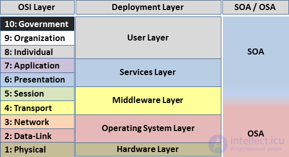
Layer 8, or the eighth layer, is a layer of the OSI model located at its top and denoting the "user" or "political" layer.
According to Bruce Schneier and RSA Security, the user layer is divided into:
Political economy theory holds that the eighth layer is very important for understanding the OSI model. Political institutions such as net neutrality, spectrum management and digital inclusion all involve technologies of layers 1-7 of the OSI model.
The eighth layer also includes references to physical controllers that contain an external hardware device for interacting with the network in the OSI model. An example is the ALI in Profibus. Category: Computer network architecture
OSI user layers
In the TCP/IP model, the four-layer model of the Internet, the fifth layer can likewise occasionally be described as the "political layer" (and the sixth as the "religious layer"); these appeared in RFC 2321, a humorous April Fools' RFC published in 1998.
Linux Gazette ran a regular Layer 8 column in Linux Security.
Layers 8, 9 and 10 are sometimes used to represent individuals, organizations and governments for the user layer in service-oriented architecture
1. Which OSI layer is responsible for the physical transmission of data?
2. Which OSI layer provides reliable data transfer between nodes?
3. Which OSI layer is responsible for routing packets?
4. Which OSI layer is responsible for managing sessions between applications?
5. Which OSI layer is responsible for data formatting and encoding?
6. Which OSI layer provides the interface for applications?
7. Which OSI layer is responsible for managing data flows?
8. Which OSI layer enables interaction between different network devices?
9. Which OSI layer is responsible for transmitting bits over a physical channel?
10. Which OSI layer works with network addresses?
11. Which OSI layer is responsible for transmitting messages between applications?
12. Which OSI layer performs data encryption and compression functions?
13. Which OSI layer establishes and terminates sessions between applications?
14. Which OSI layer handles error and flow control?
15. Which OSI layer provides independence from specific network technologies?
16. Which OSI layer provides access to application services?
17. Which OSI layer uses MAC addresses to control access to the transmission medium?
18. Which OSI layer is responsible for forming and transmitting data frames?
19. Which OSI layer manages connections between network nodes?
20. Which OSI layer includes mechanisms for data protection?

Comments