
Lecture 48 min.
Error-correcting coding is coding designed for transmitting data over noisy channels, providing correction of possible transmission errors caused by noise.
Error-detecting codes are used to detect errors, and error-correcting codes to correct them.
For 50 years the Hamming code has been called the first error-correcting code. In addition to being used in error-correcting coding standards, bit interleaving schemes in the stream are applied to reduce the formation of error bursts, as is additional Gray coding of symbols before modulation.
In continuous codes the transmitted information sequence is not divided into blocks. Redundant elements are placed in a certain order among the information elements.
Uniform block codes are divided into separable and non-separable. In separable codes the elements of the information and check parts of a codeword always occupy fixed positions. In non-separable codes there is no division into information and check bits.
Separable codes, in turn, are divided into systematic (linear) and non-systematic (nonlinear). Systematic codes are separable block (n,k) codes in which the check elements are linear combinations of the information elements; non-systematic codes do not have this property.
Error-correcting coding involves introducing into the transmitted message, along with the information bits, so-called check bits, generated in error protection devices (encoders at the transmitting end, decoders at the receiving end). Redundancy makes it possible to distinguish an allowed codeword from a forbidden one (corrupted by errors) at reception; otherwise one allowed codeword would turn into another.
An error-correcting code is characterized by a triple of numbers (n, k, d0), where n is the total number of bits in the transmitted message, including check bits (r), k=n-r is the number of information bits, and d0 is the minimum code distance between allowed codewords, defined as the minimum number of differing bits in those codewords. The number of detectable (tj) and/or correctable (t) errors (bits) is related to the parameter d0 by the relations
Sometimes additional redundancy measures derived from the characteristics n, k above are used: R = r/n is the relative redundancy, v = k / n is the relative transmission rate.
Existing error-correcting codes can be divided into a number of groups, only some of which are used to detect errors in packets transmitted over a network. In the group of systematic (linear) codes, the common property is that any allowed codeword can be obtained as the result of linear operations on linearly independent vectors. This simplifies the hardware and software implementation of these codes and increases the speed of the required operations.
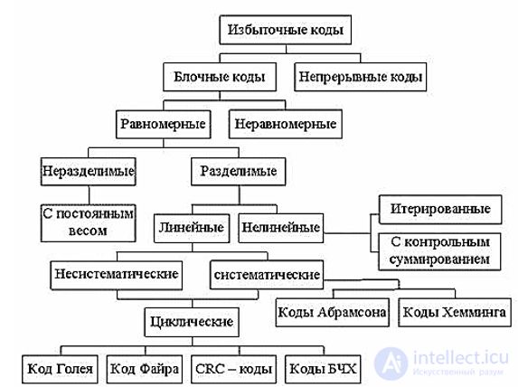
Fig. 1.1. Classification of error-correcting codes
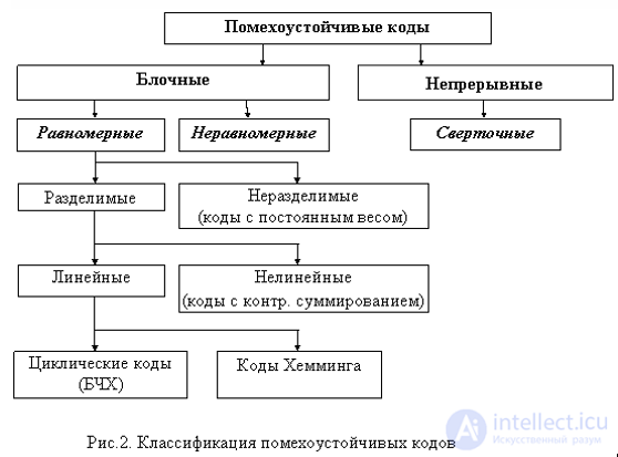
The simplest systematic codes are the even/odd parity bits. They cannot detect errors of even multiplicity (i.e. errors in two, four, etc. bits at the same time) and are therefore used when the requirements for the fidelity of the received data are modest (or when the probability of errors in the transmission line is low). An example is the Parity bit in the serial port mode settings using the MODE command (MS DOS). Despite their limited error-detection capabilities, parity bits are of great importance in the theory of error-correcting coding. One of the first mathematically grounded and practically used error-correcting codes, Hamming codes are simply a set of cross parity checks. Cyclic codes can be regarded as generalized parity checks.
Claude Shannon formulated a theorem for the transmission of discrete information over a noisy communication channel, stating that the probability of erroneous decoding of received signals can be made arbitrarily small by choosing a suitable method of encoding the signals. Shannon's theorem does not say how error-correcting codes should be constructed. However, it points out the fundamental possibility of coding that can provide arbitrarily high transmission fidelity. This was the stimulus for the development of error-correcting codes.
The noise immunity of coding is provided by introducing redundancy into the codewords, i.e. by the fact that not all symbols in the codewords are used to carry information.
All error-correcting codes can be divided into two main classes: block and continuous (recurrent or chain) codes.
In block codes each message (or message element) is assigned a codeword (block) of a certain number of bits. Blocks are encoded and decoded separately from each other.
Block codes may be uniform, when the length of the codewords n is constant, or non-uniform, when n is not constant.
In continuous codes redundancy is introduced into the sequence of input symbols without splitting it into separate blocks. The encoding and decoding processes in continuous codes are also continuous in nature.
Both block and continuous codes, depending on the methods of introducing redundancy, are divided into separable and non-separable. In separable codes the roles of individual symbols are clearly delineated. Some symbols are information symbols, others are check symbols and serve to detect and correct errors. Separable block codes are usually called n,k-codes, where n – is the length of the codewords and k – is the number of information symbols in the codewords.
Non-separable codes have no clear division of the codeword into information and check symbols.
Separable block codes are divided, in turn, into non-systematic and systematic. Non-systematic separable codes are constructed so that the check symbols are determined as the sum of subblocks of length l, into which the block of information symbols is divided.
Most known separable codes are systematic codes. In these codes the value of the check symbols is determined by performing linear operations on certain information symbols. For binary codes, each check symbol is chosen so that its modulo-two sum with certain information symbols becomes zero (i.e. the number of ones is even). Decoding reduces to parity checks on certain groups of symbols. As a result of such checks, information is given about the presence of errors and, if necessary, about the positions of the symbols in which errors occur.
Block code - in computer science, a type of channel coding. It increases the redundancy of a message so that at the receiver it can be decoded with minimal (theoretically zero) error, provided that the information transmission rate (the amount of information transmitted in bits per second) does not exceed the channel capacity.
The main characteristic of a block code is that it is a fixed-length channel code (unlike source coding schemes such as Huffman coding, and unlike channel coding methods such as convolutional coding). Typically, a block coding system receives at its input a k-symbol word W and converts it into an n-symbol codeword C(W). This codeword is called a block.
Block coding was the main type of coding used in early mobile communication systems.
The sequence of incoming information symbols  is divided into segments (blocks), each containing
 symbols:

In the encoder each individual block is converted into a new block:

The conversion rule (the functional dependence, denoted here by the letter  ) for each incoming block does not depend on the contents of the other incoming blocks; the blocks obtained as a result of the conversions
Example. Suppose the alphabet of a language consists of five letters: a, v, l, o, s. They can be encoded into a numeric sequence by the rule:  a
a  ,
, v
v  ,
, l
l ,
,  o
o ,
,  s
s . In this case the code length is
  . A recipient to whom the numeric sequences are dictated over the telephone
 or
or 
decodes them unambiguously, provided he knows the encoding rule. Clearly, encoding the whole Russian alphabet would require two-digit decimal numbers, i.e.  (and note, just in case, that encoding by the rule
 a
a ,
,  b
b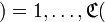 ya
ya would no longer be correct...). For now we will stay with the example of the five-letter alphabet to show two problems. Suppose the telephone line is subject to noise and some messages may be lost:

or else corrupted

Can the lost information be recovered? Clearly, the answer to this question depends first of all on the transmission characteristics of the communication channel itself.
The question of the minimum redundancy at which a code has the required error-correcting properties is one of the most important in coding theory. This question has still not been fully resolved. In
the present day only a number of upper and lower bounds have been obtained, which establish the relationship between the maximum possible minimum distance of an error-correcting code and its redundancy.
The trade-off between efficiency (a higher information transmission rate) and correcting ability can also be seen by trying to fix the codeword length and a fixed correcting capability (represented by the Hamming distance d) and maximizing the total number of codewords. [n, d] is the maximum number of codewords for a given codeword length n and Hamming distance d..
The Hamming distance between two codewords  and
and is the number of positions in which these words differ from each other. As a rule, in what follows the elements of codewords will be binary code symbols, i.e.
 and
and are vectors consisting of zeros and ones. The Hamming distance between such vectors is equal to
 . For any such vector
 itsHamming weight is the number of nonzero coordinates, i.e.
  .
.
Example. The Hamming distance between the vectors  and
and is equal to
 .
.
In what follows we will often write binary vectors without separating their elements by commas.
The definition introduced allows us to give a geometric interpretation of the solution of the last example. The encoding table from it contains all binary vectors consisting of five elements whose distance from the vector in the top row and the corresponding column is equal to  . We can say that the vector of each column is contained in the neighborhood of size
 of the corresponding vector
 . The latter are so well chosen that these neighborhoods do not intersect. The vector at the channel output is checked for falling into one of the neighborhoods; if so, it can be decoded into the corresponding letter (the "center" of the neighborhood), and if not, one can try comparing the Hamming distances to all these centers and decoding into the nearest one...
Example. Suppose the alphabet of a language consists of five letters: a, v, l, o, s. They can be encoded into a numeric sequence by the rule:  a
a  ,
, v
v  ,
, l
l  ,
, o
o  ,
, s
s  . In this case the code length is
 . A recipient to whom the numeric sequences are dictated over the telephone
 or
or 
decodes them unambiguously, provided he knows the encoding rule. Clearly, encoding the whole Russian alphabet would require two-digit decimal numbers, i.e.  (and note, just in case, that encoding by the rule
 a
a  ,
, b
b 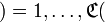 ya
ya  would no longer be correct...). For now we will stay with the example of the five-letter alphabet to show two problems. Suppose the telephone line is subject to noise and some messages may be lost:

or else corrupted

Can the lost information be recovered? Clearly, the answer to this question depends first of all on the transmission characteristics of the communication channel itself.
We now move on to encoding the letters in the binary system:  a
a  ,
, v
v  ,
, o
o  ,
, s
s  , forgetting for now about the fifth letter. Thus the code length is
 . Suppose that for each transmitted codeword the communication channel introduces at most one error: in each block of length 2 it may change
 to
to or
or to
to , but not both bits at once (and it does not erase a bit completely). What can happen when the encoded message is transmitted

over such a channel? The receiver may see the following variants:
 or
or  or
or
but will not receive the following:
 or
or 
So the choice of the most economical coding method, in which four binary blocks correspond to the four symbols of the alphabet, does not solve the problem of reliable communication. Let us increase the code length, let  a
a  ,
, b
b  ,
, o
o  ,
, c
c  . What can happen to these codewords when exactly one error is introduced into them? Let us build a table of all possible situations:
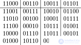
Note that the columns do not contain identical blocks. Thus, if the condition that a block is corrupted by no more than one error holds, the decoder can unambiguously recover the transmitted letter: it is enough to find the column of the table that contains the received block.
This example illustrates an error-correcting code, in this case one that corrects a single error. What happens if the channel noise turns out to be higher than assumed? There may be situations where the block received as a result of transmission is contained in the table. For example, if the block  is fed to the input and the channel corrupts two bits, the receiver may see the block
 , which, although it is contained in the table, is decoded into a completely different letter from the one that was transmitted. It may also happen that the block
 comes out of the channel, which is not contained in the table at all. This situation is sometimes more favorable than the previous one: the decoder can be made to notify the user that an error has been detected when the received block is not contained in the table. It is possible to build both capabilities into the decoder at once: error signaling and error correction. Let us see what can be done using the received block
 as an example. Note that this block differs from the sent block
 a
a  in two bits, from the block
 b
b  also in two bits, and from each of the blocks
 o
o  or
or c
c  in three bits. Therefore, given the hypothesis of no more than two corrupted bits, the last two variants can be discarded during decoding as impossible.
When block codes are used, digital information is transmitted as separate codewords (blocks) of equal length. Each block is encoded and decoded independently of the others.
Almost all block codes are separable codes, whose codewords consist of two parts: an information part and a check part. With a total of n symbols in a block, the number of information symbols is k, and
the number of check symbols is r = n – k. The main characteristics of error-correcting codes include:
− the number of allowed and forbidden codewords;
− the redundancy of the code;
− the minimum code distance;
− the number of detectable or correctable errors;
− the error-correcting capabilities of the codes.
Systematic codes form the most extensive group of (n, k) separable codes. A feature of these codes is that the check (error-correcting) symbols are formed by linear operations on the information symbols. In addition, any allowed codeword can be obtained as a result of a linear operation on a set of k linearly independent codewords. In particular, the modulo-2 sum of two or more allowed words also gives an allowed codeword. Since the theoretical basis for obtaining such words is the mathematical apparatus of linear algebra, these codes are called linear, and since the check symbols are formed according to a certain system
(rules), uniform-length separable linear block codes came to be called systematic. The use of the apparatus of linear algebra, in which the concept of a "group" is important, also gave rise to another name for these codes: group codes. These codes have found the widest application in discrete information transmission systems.
The Hamming code is one of the first error-correcting codes capable of correcting one or several errors. It is a block code. Let us briefly recall the main parameters of the Hamming code:
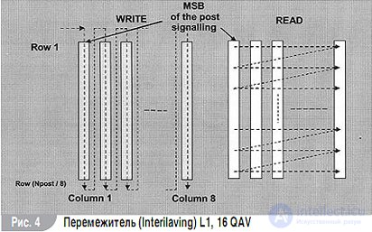
The code corrects single errors. To correct error bursts, an interleaving system is used. The idea of the method is to scatter the symbols of a codeword. The symbols must be placed at such a distance from one another that they are subject to independent fading [1, 2, 12]. With independent fading, the affected symbols will belong to different codewords. This makes it possible to correct errors using the original code. Several kinds of interleaving are known in the literature. In it, codewords are placed as rows of a rectangular matrix and are read out by columns (Fig. 4).
Note. No method has been found in coding theory for passing from the maximum Hamming distance dmin to the Euclidean distance de.
Redundant bits n-k are always introduced into error-correcting codes. They are used as a means of control (parity bits, check bits). The ratio of the number of redundant bits to the number of information bits (n-k)/k is called the redundancy of the code. The ratio of the number of data bits to the total number of bits, k/n, is the code rate. The maximum amount of redundancy of a code must not exceed T= r/1-r, where r = r-k/n.
The receiver's detector must start operating after the first symbol of the code sequence is received.
The source encoder replaces the information words u at its output with the codeword v. The receiver performs the inverse transformation. As a result, the binary received word r arrives at the decoder.
A binary (n, k) block encoder maps the set of 2k possible binary words into a set of 2n-dimensional codewords.
The duration of a codeword equals the time interval during which a block of K information symbols appears at the channel input.
All columns of the parity-check matrix must be pairwise distinct. The rows of the generator matrix must contain at least three ones, since the rows of the generator matrix are codewords.
In coding there is the notion of a good code. A good code is a code that has the largest number of information symbols for a fixed code length and minimum distance dmin.
A cyclic code is a code whose set of codewords is represented by a collection of polynomials of degree n-1 or less that are divisible by some polynomial G(x) of degree n-k, which is a factor of the binomial Xn +1.
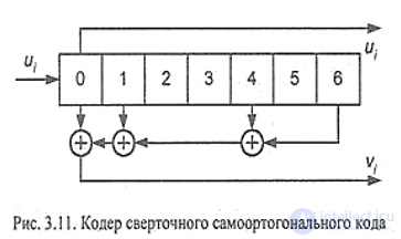
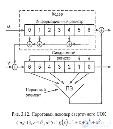
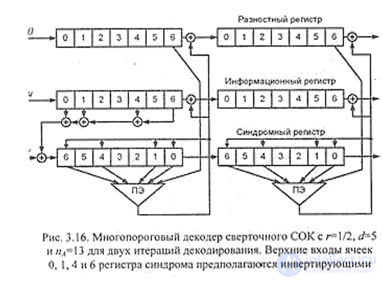
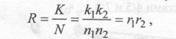
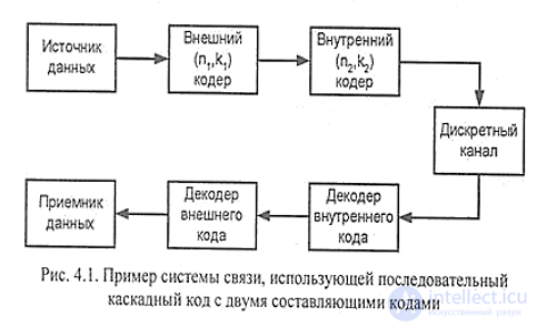
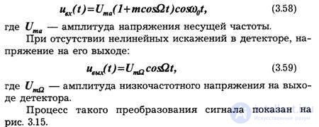
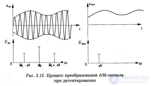
In operations with cyclic codes, the codeword B = bn-1, bn-2 …b1b0 ) is represented as a polynomial B(X) of degree B(x) = bn-1xn-1 + bn-2xn-2 + b1x+ b01. The polynomial g(x) is usually called the generator polynomial of the cyclic code. The parity-check matrix is defined as: H(x) = (xn+1)/g(x) [8-10] For the Hamming (7,4) code Note. The polynomial Xn+1 is divisible by Xm if and only if n is divisible by m. Codes in which error correction is possible are called perfect. A polynomial P(x) of degree m is called irreducible over GF(2) if it is not divisible by any polynomial with coefficients from GF(2) of degree less than m but greater than 0. An irreducible polynomial P(x) is called primitive if the smallest degree n for which the polynomial Xn+1 is divisible by it without remainder is n = 2m-1. Block codes are created on the basis of the generator matrix G(x) or the generator polynomial g(x). In these codes, each codeword is represented by a polynomial whose coefficients are the elements of the codeword. The error-correcting Hamming code (n, k, t) includes only those codewords whose polynomials are divisible by one and the same polynomial g(x) of degree n-k. This polynomial is called the generator polynomial. C(x) = a (x) g(x). The degree of the polynomial is checked using the parity-check matrix H(x). G(x). Ht (x) = 0 indicates the absence of errors, and the degree of a(x) does not exceed k-1. Error control is carried out using syndromes: A syndrome is the result of a parity check performed on the signal r to determine whether it belongs to a given set of words. In the absence of errors, the syndrome is zero. The encoding process of a block code consists of splitting the information sequence into messages of length k and mapping these messages into codewords. C = C0, C1…Cn-1. The word is obtained as C = UG. The information bits are always placed at the beginning of each word. (Xn-1, Xn-2, Xn-3 the last n-k Xn=r=1, Xn-k-2, Xn-k-3 will be the check bits). The parity-check polynomial is H(x) = (xn+1)/g(x). The detection of decoding errors of block codes is widely covered in [1, 3-6]. Binary Hamming codes 2m-1; 2m-m-1 can be constructed on the basis of the roots a of a primitive element of the field GF(2m ): α2m-2, α2m-3...α. A cyclic code is a linear code with the cyclicity property, that is, every cyclic permutation of a codeword is also a codeword. It is used to transform information in order to protect it from errors A class of linear codes called cyclic codes has become widespread in practice. This name comes from the main property of these codes: if some codeword belongs to a cyclic code, then the word obtained by a cyclic permutation (cyclic shift) of the original word also belongs to that code. The second property of all allowed words of cyclic codes is that they are divisible without remainder by some chosen polynomial, called the generator polynomial. The error syndrome in these codes is the presence of a remainder from dividing the received codeword by the generator polynomial. These properties are used in constructing codes and encoding and decoding devices, as well as in detecting and correcting errors. Representing a codeword as a polynomial. It is convenient to describe cyclic codes and construct them using polynomials. In the theory of cyclic codes, codewords are usually represented as polynomials. Thus, an n-element codeword can be described by a polynomial of degree (n-1), in the form where Let us write the polynomials for specific 4-element words Block diagram of the (9,5) cyclic code encoder The complete block diagram of the encoder is shown in the following figure. It contains a delay register and the check-group generator considered above. Let us consider the operation of this circuit 1. In the first stage, K1 is closed and K2 is open. The delay and shift registers are filled simultaneously with information elements (most significant first!), and after 4 clock cycles the most significant bit is in cell No. 4 2. During the fifth clock cycle, K2 closes and K1 opens; from this moment the remainder is formed in the check-group generator (CGG). At the same time, the delayed information bits are pushed out of the delay register to the output. In 5 clock cycles (from the 5th through the 9th inclusive), all 5 information elements go out onto the line. By this time the remainder is formed in the CGG 3. K2 opens, K1 closes, and the elements of the check group go out onto the line after the information elements. 4. At the same time, the registers are filled with a new word. The second way of building a cyclic code encoder. The encoder considered above very clearly reflects the process of dividing binary numbers. However, it is possible to build an encoder with fewer elements, that is, a more economical one. A device for division by the generator polynomial In five clock cycles, the cells will hold the same remainder of the division as in the check-group generator (CGG) considered above. During the same 5 clock cycles, the information bits are output directly to the modulator. Then the check bits from the cells of the division device follow the information bits. But it is important to disconnect the feedback at the moment the check elements are output; otherwise they will be distorted. The final block diagram of the economical encoder looks like this. - On the first clock cycle, Sw.1 and Sw.3 are closed, the information elements pass to the encoder output, and at the same time the check elements are formed. - After the fifth information element has gone out onto the line, the check elements are formed in the division device; - on the sixth clock cycle, switches 1 and 3 open (the feedback is broken), switch 2 closes, and the check bits go out onto the line. The cells are filled with zeros, and the circuit returns to its initial state. Suppose we have n-element words (n = k + r). Then: 1. Obtain the remainder R0(x) of dividing E(x), corresponding to an error in the most significant bit [1000000000], by the generator polynomial Pr(x) 2. Divide the received polynomial H(x) by Pr(x) and obtain the current remainder R(x). 3. Compare R0(x) and R(x). - If they are equal, the error occurred in the most significant bit. - If not, increase the degree of the received polynomial by X and perform the division again b) Again compare the resulting remainder with R0(x) - If they are equal, the error is in the second bit. - If not, multiply H(x) by x2 and repeat these operations until R(X) equals R0(x). The error is in the bit position equal to the number by which the degree of H(x) was raised, plus one. For example: Convolutional codes are a very important class of error-correcting codes. They are increasingly used in digital communication systems. One of their main advantages is the simplicity of the encoding procedure and well-known decoding techniques, both soft-decision and hard-decision. In terms of logic circuit theory, the encoder of convolutional codes (hereafter, the convolutional encoder) is an automaton. It has a certain number of states, into which it moves depending on the input information bits, which are treated as control signals. The output signal, which is a codeword, is the result of the encoder's transition from the current state to an adjacent one. A convolutional encoder is a device that, at each clock cycle, accepts in the general case k input information symbols and outputs n output symbols per cycle. The number is called the relative code rate. k is the number of information symbols, n is the number of symbols transmitted to the communication channel per clock cycle in which an information symbol arrives at the encoder. The output symbols of the cycle in question depend on m information symbols arriving in this and the previous cycles; that is, the output symbols of a convolutional code are uniquely determined by its input symbols and by the state, which depends on m — k previous information symbols. The main elements of a convolutional code are: a shift register, a modulo-2 adder, and a commutator. A shift register (Shift register) is a dynamic storage device that holds the binary symbols 0 and 1. The memory of the code determines the number m of trigger cells in the shift register. When a new information symbol arrives at the input of the shift register, the symbol stored in the rightmost cell is shifted out of the register and discarded. The remaining symbols move one cell to the right, and thus the leftmost cell is freed, into which the new information symbol will enter. A modulo-2 adder adds the symbols 1 and 0 arriving at it. The rule of modulo-2 addition is as follows: the sum of binary symbols is 0 if the number of ones among the symbols arriving at the inputs is even, and 1 if this number is odd. A commutator sequentially reads the symbols arriving at its inputs and sets the order of the code symbols on the output into the communication channel. By analogy with block codes, convolutional codes can be classified into systematic and nonsystematic. A systematic convolutional code is a code whose output sequence of code symbols contains the sequence of information symbols that generated it. Otherwise the code is called nonsystematic. The main advantage of convolutional encoders is the noise immunity of the sequence they produce. The point is that, thanks to redundancy, the original bit sequence can be recovered without errors. The Viterbi decoder is used to recover the original bit sequence at the receiver side. Diagram of a convolutional encoder (K = 7); the code rate is 1/2. The Viterbi decoding algorithm is designed for decoding convolutional codes and is optimal in the sense of minimizing the sequence error probability. The main idea of the Viterbi algorithm is to compare, step by step, all paths through the code trellis with the sequence Y received from the channel, and to discard those that will certainly be at a greater distance than other paths. Let us describe the operation of the Viterbi algorithm while the i-th n0-symbol group of the sequence Y is being received from the channel. By this moment, the paths under consideration may pass through 2k-1 nodes (states) of the trellis diagram (here K— is the constraint length of the code), and for each of them the distance from the received sequence has been computed (from here on we will call this distance the metric). At the i-th step it is necessary to: 1. Compute the Hamming distance between the received n0-symbol group and all possible branches of the trellis diagram. Since two branches leave each of the 2K-1 nodes, 2K such distances must be computed. 2. The Hamming distances for each of the branches are added to the metrics of the paths from which they leave. This yields 2K possible paths leading into 2K-1 states. 3. For each of the 2K-1 states, the metrics of the two paths entering it are compared, and the path with the smaller metric, that is, the one at a smaller distance from the input sequence, becomes the survivor. The path with the larger metric is discarded and takes no part in further computations. 4. Store all 2K-1 survivor paths together with their metrics and proceed to step (i+1). Sequential decoding algorithms Another method of decoding convolutional codes is the sequential decoding algorithm. In operation, the sequential decoding algorithm, unlike the Viterbi algorithm, processes only the most probable path through the code trellis. If the decoder makes an error at some decoding step, the distance between the current path and the received sequence begins to increase rapidly. Noticing this, the decoder goes back one or several steps and tries to find a more correct solution. To detect an incorrect path quickly and correct it quickly, the decoder parameters must be chosen very carefully. Threshold decoder These codes, like the block self-orthogonal codes (SOC) described earlier, are usually defined by generator polynomials whose difference triangles contain no identical elements. Just as for block codes, threshold decoding is applicable to convolutional self-orthogonal codes. The scheme of the threshold decoder for a convolutional SOC, whose encoder is shown in Fig. 3.11, is shown in Fig. 3.12. As can be seen from the figure, the decoder consists of an encoder, a syndrome register, and a threshold element. The error correction procedure of this decoder generally coincides with the operation of the threshold decoder of a block SOC, except that on moving on to decoding the next information symbol, an ordinary shift of the component registers is performed rather than a cyclic one. Multithreshold decoder The multithreshold decoding method, presented in Section 2.8, can be used for decoding convolutional self-orthogonal codes. In this case the decoder will consist of several serially connected decoding blocks (Fig. 3.16). The multithreshold decoder (MTD) for a convolutional SOC shown in Fig. 3.16 contains only two decoding iterations, but it can easily be converted into an MTD with a larger number of iterations simply by adding a few more decoding blocks whose block diagram is exactly the same as that of the second decoding block. An important stage in the development of coding theory was the appearance of concatenated codes [24], the construction of which is based on the idea of jointly using several component codes. This approach made it possible to significantly increase the efficiency of coding compared to basic non-concatenated methods. An example of using a concatenated code consisting of two component codes is shown in Fig. 4.1. Here the source data is first encoded by an outer (n1, k1) code. Non-binary codes, for example Reed-Solomon codes, are often used as the outer code. Then the encoded symbols of the outer code are encoded by the encoder of the inner (n2, k2) code. The total codeword length of the concatenated code turns out to be N=n1n2 binary symbols, of which K=k1k2 are information symbols. Consequently, the code rate of the resulting concatenated code is equal to where r1, r2 — are the code rates of the component encoders. Note also that the minimum distance of the resulting concatenated code will be equal to D=d1d2, where d1 and d2 are the minimum distances of the component codes. Decoding of a concatenated code is performed in the reverse order, that is, the one received from the channel is first decoded by the inner-code decoder, and the resulting sequence is then decoded by the outer-code decoder. Note that although the total code length is N, the structure of the concatenated code makes it possible to use two decoders for codes of lengths of only n1 and n2 respectively. This property significantly reduces decoding complexity compared with non-concatenated block or convolutional codes of comparable performance. A turbo code is a parallel concatenated systematic block code capable of correcting errors that occur when digital information is transmitted over a noisy communication channel. A synonym for turbo code in coding theory is the term concatenated code. A turbo code consists of a cascade of systematic codes connected in parallel. These constituents are called component codes. Convolutional codes, Hamming codes, Reed-Solomon codes, Bose-Chaudhuri-Hocquenghem codes and others can be used as component codes. Depending on the choice of component code, turbo codes are divided into convolutional turbo codes and block product codes. Turbo codes were developed in 1993 and are a class of high-performance error-correcting codes used in electrical engineering and digital communications. They have also found application in satellite communications and in other areas where the maximum data rate over a noisy channel in a limited frequency band must be achieved. Advantages. Among all practically used modern error-correction methods, turbo codes and low-density parity-check codes come closest to the Shannon limit, the theoretical limit of the maximum capacity of a noisy channel. Turbo codes make it possible to increase the information transmission rate without increasing transmitter power, or they can be used to reduce the power required to transmit at a given rate. An important advantage of turbo codes is that the decoding complexity does not depend on the length of the information block, which makes it possible to reduce the decoding error probability by increasing that length. Disadvantages. The main disadvantage of turbo codes is their relatively high decoding complexity and long delay, which make them inconvenient for some applications. For satellite channels, however, this drawback is not decisive, since the length of the communication link itself introduces a delay caused by the finite speed of light. Another important disadvantage of turbo codes is their comparatively small code distance (that is, the minimum distance between two codewords in terms of the chosen metric). As a result, although a turbo code performs well when the input error probability is high (that is, in a bad channel), its performance is extremely limited when the input error probability is low.[10] Therefore, in good channels, LDPC codes rather than turbo codes are used to reduce the error probability further. Although the complexity of the turbo coding algorithms used and the lack of open-source software hinder the adoption of turbo codes, many modern systems now use them. Applications of turbo codes. France Telecom and Telediffusion de France have patented a broad class of turbo codes, which limits the freedom to use them and, at the same time, stimulates the development of new coding methods such as LDPC. Turbo codes are widely used in satellite and mobile communication systems, broadband wireless access and digital television. Turbo codes are approved in the DVB-RCS satellite communication standard. Turbo codes have also found wide use in third-generation mobile communication systems (the CDMA2000 and UMTS standards). The main tasks of adaptive modulation and coding are to compensate for radio channel instability and to fine-tune the transmission parameters. Various methods and means exist for improving radio channel adaptation, for example power control, adaptive antennas, dynamic coding, channel allocation, and so on. Although all of these methods ultimately pursue one goal, they are implemented differently and can therefore be used as complementary means of achieving a positive effect. As for the AMC method, its main function is to adjust the modulation and coding characteristics in order to compensate for changes in the physical-layer channel. The advantages of an AMC system are well known, but its performance depends strongly on radio channel measurements obtained in the terminal equipment, and the measurement cycle may not coincide with the periods of ordinary channel variation during fast fading. Moreover, such measurements are not free of errors. Unreliable channel state reports can lead to wrong decisions in packet scheduling, transmit power setting, and the choice of modulation and coding type. Detection of amplitude-modulated signals AM signal detectors are intended to convert a modulated high-frequency electrical oscillation into a voltage (current) that varies according to the modulation law. Detectors based on nonlinear elements are built according to the block diagram shown in Fig. 3.14. The detected voltage is described by the equation: Let us consider qualitatively the phenomenon that occurs during продолжение следует... 


Cyclic Codes. Representing a Binary Code as a Polynomial
 .
. ={0,1}, with
 = 0 corresponding to the zero elements of the word, and
 = 1 to the nonzero ones.

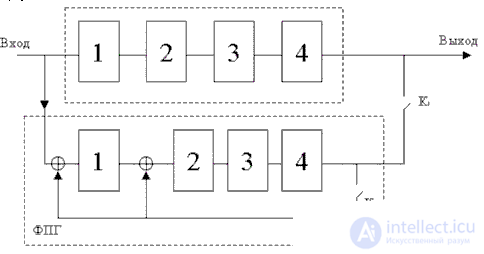
 can be implemented as follows: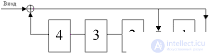
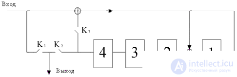
Algorithm for Determining an Error in a Cyclic Code
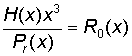 then the number of the erroneous bit is 3+1=4
Convolutional Codes: Convolutional Encoder Diagram
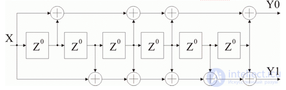
Types of Convolutional Code Decoders.
Serial Concatenated Codes
Parallel concatenated codes
Adaptive modulation and coding system
Discrete communication system with adaptive modulation and coding
Продолжение:
Часть 1 Forward Error Correction Coding Standards
Часть 2 BCH codes - Forward Error Correction Coding Standards

Comments