
Lecture 48 min.
Это окончание невероятной информации про коды ldpc.
...
detection. Assume that the nonlinear element has the current-voltage characteristic:

When an amplitude-modulated voltage is applied to the detector, a current flows in its output circuit in the form of high-frequency pulses with the envelope of the modulated oscillation (Fig. 3.17).
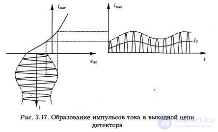
The current spectrum contains oscillations at the carrier frequency and its harmonics, a DC component, and a component at the modulation frequency. The average value of the nonlinear element current over a period of the high-frequency voltage is directly proportional to the area of the current pulse flowing through the nonlinear element during that period. The area of a sinusoidal pulse is directly proportional to its maximum value, and the envelope of the pulses corresponds in shape to the envelope of the input modulated oscillation. Therefore, the value of the nonlinear element current averaged over the high-frequency period also varies according to the modulation law. Thus, to extract a signal that varies according to the modulation law, it is sufficient to average the output current (or voltage) of the detector.
Averaging (or filtering) of the detector output voltage is performed by a load in the form of a filter made up of a resistor R and a capacitor C. The time constant of this circuit is usually chosen from the condition

When condition (3.61) is met, the detector is inertialess with respect to the modulating voltage and is therefore called inertialess. If the inequality RC << TΩ is violated, the detector becomes inertial, and as a result the modulating signal is reproduced in distorted form. The inertialess condition of the detector is usually assumed to be satisfied.
For the detection of pulsed radio signals, ordinary amplitude detector circuits are used, differing in their element parameters.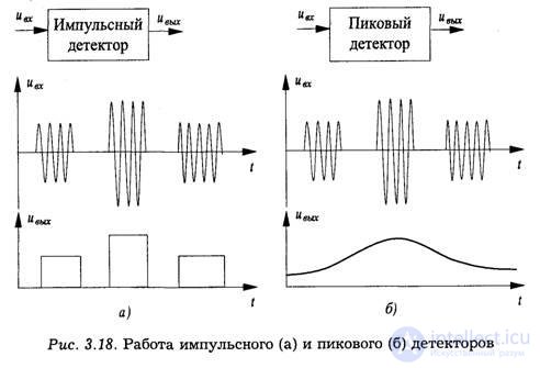
A pulsed radio signal detector performs either extraction of the envelope of each input radio pulse or extraction of the sequence of input radio pulses. In the first case, pulses
of varying amplitude (video pulses) are formed at the detector output. Such a detector is called a pulse detector (Fig. 3.18a). In the second case, the sequence of high-frequency pulses is converted into a voltage whose shape follows the envelope of the sequence. Since the output voltage in this case is proportional to the maximum (peak) amplitude of the pulses in the sequence, the detector is called a peak detector (Fig. 3.18b). Since the frequency of variation of the pulse-sequence envelope is much lower than the pulse repetition frequency, the pulse detector and the peak detector actually differ only in the time constant of the load circuit.
We take the description of how this code works from [12]; it corresponds to the creation of codecs for the standards mentioned above [9-11].
Unlike other block codes, BCH codes are defined through the roots of the generator polynomial g(x) of degree n-k.
A cyclic BCH code of length n over the field GF(q) is called a BCH code with designed distance 5 if, for some integer b 0, its generator polynomial is equal to:

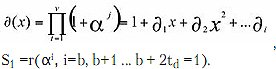
that is, a GF(g) polynomial over the field such that the elements αb, αb+1, αb+2, αb, are its roots. Consequently, the roots will be all field elements conjugate to αb+δ-2 with respect to the power 2.
BCH codes whose length is on the order of several hundred bits surpass in quality all other block codes with the same block length and code rate. G(x) = LCM{}, that is, a GF(g) polynomial over the field such that the elements are its roots. Consequently, the roots will be all field elements conjugate to α with respect to the power 2.
A cyclic BCH code is constructed on the basis of the extension field GF(2m). Its roots α, α2, where α is a primitive element of the field GF(2m), have a minimum distance dmin no less than S+1. Consequently, a BCH code is a cyclic code and its generator polynomial has 2t consecutive roots for field elements.
The construction of codewords in BCH and LDPC codes is described in [1, 7, 8, 12].
The DVB-T2 project is based on the Galois fields GF(216) for the long sequence and GF(214) for the short one. The BCH code sequence is fed into the LDPC code, which provides a multilevel constellation diagram at the output. Each polynomial of a cyclic error-correcting code can be represented as a product of polynomials of lower degrees:
F(x) = (x-β1)(x-β2)...(x-βk), where β are the roots of the polynomial F(x).
The generator polynomial g(x) can be represented in terms of the roots β.
A polynomial of minimal degree with m(β) = 0 is called irreducible.
If a polynomial with f(b) = 0 is divisible by m(β), then it will be the minimal polynomial.
The polynomial X2m-1+1 has as its roots all 2m-1 nonzero elements of GF(2m).
To choose the generator polynomials of cyclic BCH codes, as well as to determine the error-correcting properties of cyclic codes, one must know the roots of the polynomial, which can be taken as generator polynomials of the codes.
Primitive and non-primitive BCH codes are known. Reed-Solomon codes are among the non-primitive ones.
Primitive BCH codes correct t errors, n = gm - 1, over the Galois field GF(g).
In a non-primitive BCH code, the element α is replaced by β of the field GF(gm), and the block length will be -β over the Galois field GF(g).
For any positive integers m and t0≤n/2 there exists a BCH code of length n = 2m - 1 that corrects all combinations of t0 errors and contains no more than mt0 check symbols.
In a BCH code, errors are determined by position numbers. On this basis the error syndrome is determined [6-8, 12]. Thus, the generator polynomial of a binary code has the form

and the code length n is equal to:

The designed code distance is equal to 2td+1.
The lower bound of the BCH code will be d2l+1 if the polynomial p(x) has consecutive roots: αb, αb+1... αb+2.
BCH codes are decoded in the receiver by its decoders.
A signal with interference in the air arrives at the receiver: r(x) = v(x) +e(x) or r(x) = cx(x)g(x)+ S(x), where S(x) is the error syndrome.
A number of algorithms for decoding cyclic codes currently exist.
What all block decoders have in common is that the circuit consists of two branches (channels).
The main branch contains the decoder itself, an n-bit register. The second one (signal channel L1) contains the error syndrome detectors and the error correction unit.
The outputs of both channels go to a modulo-2 addition circuit. The resulting stream is subject to further processing. The decoder circuit is shown in Fig. 7 .
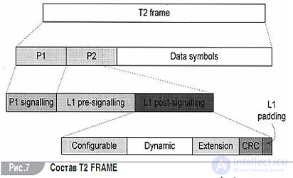
The main principle when decoding BCH in the DVB-T2 standard is to use the codeword position elements in the order of the coefficients of the associated polynomial.
The decoding number within the FECFRAME is defined as:

where Nidpc is the LDPC code number
Emat is the number of the I parity bit matrix.
C0de is the code rate (bit/s).
FcikP is the block decoder frequency.
Pdec is the number within the decoder (in Q = 360).
αdtc is the effective decoder factor.
The error positions [6-8, 12] can be found by solving a system of equations in the field GF(2m); these equations can be obtained by introducing the error polynomial e(x) and taking into account the zeros of the code for b≤j≤b+2tg - 1.
The syndromes are defined as the values of the received polynomial r(x) at the zeros of the code.
They are computed by dividing the received polynomial by g(x).
The syndromes are defined as the values of the received polynomial r(x) at the zeros of the code:
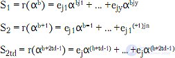
Error locator polynomial:
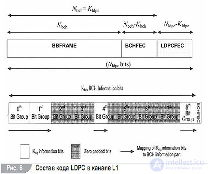
The architecture of BCH codes is shown in Fig. 6, 7.
Error locator polynomial
When computing the syndromes, one must first compute the value of the received polynomial at the zeros of the code.
A number of methods for solving this equation are known [2, 12].
The architecture of BCH codes is shown in Fig. 6.
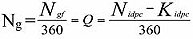
LDPC codes are low-density parity-check codes [3, 6-8, 12] with dimensions M and N, where N is the number of bits and M is the number of checks in a codeword. An LDPC code is a code whose parity-check matrix of dimension MxN contains dc M ones in each column and d Time deinterleaving into the L1 signal. The information bits Kbh forming the outer codeword (M = mkdch-1, mkdc-2, …m1, mo) pass to the LDPC FEC encoder (Nipc – Kidpc), the inner word LDPC I = (i0, i1,…iNbhc-1) = (mKdch-1, mKdch-2…m1, m0, dNdch=Kdch-1, dNdch= Kdch-2,…d1, d0) being equivalent to the codeword of the polynomial C(x) = XNbch-Kbch m(x)+d(x). The inner FEC FRAME encoder forms the parity bit difference: for each block of information bits. It is assumed that P0 = P1 =…PNidpc-Kidpc = 0. The accumulation of the first information bit with the parity bit of the same number must sum modulo 2 to 0. This means there is no error. The outer bits connected to the zero ones together with the parity bits form the bits I [13]. The method of constructing the matrix H consists in dividing the words into groups of Q = 360 bits. The even-numbered bits are punctured and are not transmitted further. The number of an incorrectly transmitted bit is determined on the basis of a series of computations. 1. Determination of the parity group. where 0≤Ngr≤Nidpc-Kidps. 2. Npunc of parity bits is determined as Pπ0, Pππ1 where π is the delay determined by the code rate. Here πp is the constant puncturer operator for the code rate of the outer modulator. 3. Determination of the parity bits for the puncturing group Pπ = N-360xNp. The zero bits (Kbch - Ksig) are removed without being transmitted. The resolving word of the information bit is followed by 168 BCH and (Nidpc-Kpun) LDPC parity bits There are also other algorithms for finding and correcting errors

References
Продолжение:
Часть 1 Forward Error Correction Coding Standards
Часть 2 BCH codes - Forward Error Correction Coding Standards

Comments