
Lecture
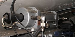
Travelling-wave tube (TWT) — an electrovacuum device in which the interaction between a travelling electromagnetic wave and an electron stream, moving in the same direction, is used to generate and/or amplify microwave electromagnetic oscillations (as opposed to a backward-wave tube (BWT)).
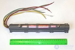
The travelling-wave tube was first created by Rudolf Kompfner in 1943 (according to other sources, in 1944).
Travelling-wave tubes are divided into two classes: O-type TWT and M-type TWT.
In O-type devices, the kinetic energy of the electrons is converted into microwave field energy as a result of the electrons being decelerated by this field. The magnetic field in such tubes is directed along the direction of beam propagation and serves only to focus the latter.
In M-type devices, the potential energy of the electrons, which shift as a result of repeated deceleration and acceleration from the cathode to the anode, is converted into microwave field energy. The average kinetic energy remains constant in this process. The magnetic field in such devices is directed perpendicular to the direction of beam propagation.
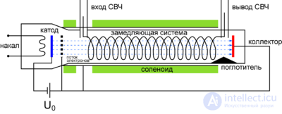
The principle of operation of travelling-wave tubes (TWTs) is based on the mechanism of prolonged interaction between the electron stream and the field of a travelling electromagnetic wave. The figure schematically shows the design of the TWT. The electron gun forms an electron beam with a specific cross-section and intensity. The velocity of the electrons is determined by the accelerating voltage. With the help of a focusing system that creates a longitudinal magnetic field, the necessary transverse cross-section of the beam is maintained along the entire path of the slow-wave structure. In a TWT, the electron gun, the helical slow-wave structure, and the collector are housed in a metal-glass or metal envelope, while the focusing solenoid is located outside. The helix is mounted between dielectric rods, which must have low microwave losses and good thermal conductivity. The latter requirement is important for medium- and high-output-power tubes, when the helix heats up due to electron deposition and this heat must be removed to prevent the helix from burning through.
At the input and output of the slow-wave structure there are special devices for matching it to the transmission lines. The latter can be either waveguide or coaxial. The microwave signal arrives at the input, is amplified in the device, and is delivered from the output to the load.
It is difficult to obtain good matching over the entire amplification band of the tube. Therefore there is a risk of internal feedback arising due to reflection of the electromagnetic wave at the ends of the slow-wave structure, in which case the TWT may cease to perform its function as an amplifier. To eliminate self-excitation, an absorber is introduced, which can be made in the form of a rod of absorbing ceramic or in the form of absorbing films.
The gain parameter — a dimensionless coefficient:
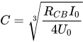 , where
  — coupling impedance,
  — cathode current, and
  — the potential of the last anode of the TWT's electron gun.
The values of C are ~0.1—0.01.
The gain factor of a TWT in the linear regime is directly proportional to the parameter C.
The practically achievable gain factor of a medium- and high-power O-type TWT is 25-40 dB, i.e. somewhat lower than that of multi-cavity klystrons (60 dB). In low-power O-type TWTs the gain factor can reach 60 dB.
A particularly valuable property of TWTs is their wide bandwidth. The gain factor of a TWT, at a constant accelerating voltage, can remain almost unchanged over a wide frequency band — on the order of 20—50% of the mean frequency. In this respect TWTs considerably surpass amplifying klystrons, which can provide very high gain but have a considerably narrower frequency band.
Depending on their intended use, TWTs are produced with output powers ranging from fractions of a mW (low-power, low-noise input TWTs in microwave amplifiers) to tens of kW (high-power output TWTs in microwave transmitting devices) in continuous-wave mode, and up to several MW in pulsed mode of operation.
Low- and medium-power O-type TWTs use helical slow-wave structures, while high-power O-type TWTs use chains of coupled cavities.
Electrons, flying through the slow-wave structure, give up part of their kinetic energy to the microwave field, which leads to a decrease in electron velocity. But this disrupts the phase-synchronism condition Ve ≅ Vph. From this follows the main limitation on the efficiency of an O-type TWT, connected with the impossibility of transferring all of the electrons' kinetic energy to the microwave field: the electron bunches shift from the decelerating-field region into the accelerating-field region.
The lower limit of the electron velocity is determined by the phase velocity of the slow wave. Therefore the efficiency value must be greater the more significantly the initial electron velocity exceeds the phase velocity of the wave in the slow-wave structure. However, as the desynchronization increases, bunching at the input section of the slow-wave structure worsens and the gain factor drops sharply. Thus, the requirements of maximum efficiency and high gain factor in an O-type TWT turn out to be contradictory.
The actual efficiency value for an O-type TWT is 30—40%.
Low-power O-type TWTs are used in input amplifiers, medium-power ones in intermediate amplifiers, and high-power ones in output amplifiers of microwave power.
In an M-type TWT, unlike an O-type TWT, there are two essential features:
. In an M-type TWT, however, the kinetic energy of the electrons does not change, and it is the potential energy of the electrons that is transferred to the field.The injecting device, consisting of a heated cathode and a control electrode, provides for the formation of a ribbon-shaped electron stream and its introduction into the interaction space.
The interaction space, consisting of a waveguide input, an absorber, a slow-wave-structure anode, a waveguide output, a collector, and a cold cathode, provides for the interaction of the electrons with the microwave field. To create such an interaction, the following condition must be satisfied
 , where
  — the initial velocity of the stream at the entrance to the interaction space,
  — the velocity of translational motion in the crossed electric (
  ) and magnetic fields (
  ).
).
When this condition is satisfied, the electrons, in the absence of a microwave field, move in a straight line toward the collector. Since the initial velocity of the stream is determined by the relation
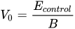 , the condition described above reduces to

The parameters of the device are chosen such that, when a microwave signal appears at the input of the slow-wave structure, the phase-synchronism condition for M-type devices is satisfied on one of its spatial harmonics (V0 = Vph). In this case, during the decelerating half-periods of the electric field of this harmonic, the energy of the microwave signal will increase at the expense of a decrease in the potential energy of the electrons. The amplified microwave signal is delivered to the output of the slow-wave structure, and the electrons are deposited on the collector.
The M-type travelling-wave tube, like the O-type travelling-wave tube, is a wideband amplifier, and therefore self-excitation is possible in it due to reflection of the amplified signal from the output of the slow-wave structure. An absorber is used to prevent self-excitation.
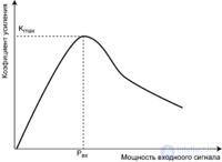
The characteristic form of the dependence of the gain factor on input power is shown in the figure. At low levels of the input signal, the amplitude of the oscillations at the output of the M-type TWT and the value of the gain factor increase directly in proportion to the magnitude of the input signal. This relationship holds until the electrons begin to land on the anode at the end of the slow-wave structure instead of the collector. In this case the growth of output power slows down and the gain factor of the M-type TWT decreases.
The gain factor in real M-type travelling-wave tubes reaches 40 dB or more.
The working frequency band in M-type TWT amplifiers reaches 30% of the mean operating frequency and is determined by the dispersion characteristic of the slow-wave structure.
The output power of an M-type TWT in continuous-wave mode reaches several kilowatts, and in pulsed mode — several megawatts.
The efficiency of an M-type TWT amplifier can be estimated based on the fact that the maximum potential energy an electron can transfer to the microwave field is {\displaystyle E_{pot}=eU_{0}} ,
,
The kinetic energy of the electron that is not given up to the microwave field:
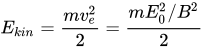
In real devices its efficiency value does not exceed 70%.
The first domestic TWT of type UV-1 was created at NII-5 of the Main Artillery Directorate of the USSR Ministry of Defense (now JSC Moscow NII of Instrument Automation (MNIIPA)). The direct executor of the work on the UV-1 was A. V. Ievsky; M. F. Stelmakh and M. A. Bruck took an active part. The UV-1 tube and its subsequent modifications, which operated in amplifier mode, were distinguished by a low noise factor, which was an outstanding achievement at the time. This was achieved by developing a special low-noise electron gun. Before this, all TWTs used so-called «Pierce guns», which had a high level of intrinsic noise. The anode of this gun was connected to the helix, which did not allow separate adjustment of the anode voltage, on which the noise strongly depended, and the helix voltage, which was selected from the need to satisfy the synchronism conditions between the slow space-charge wave in the electron beam and the field wave in the helix. M. A. Bruck developed special oxide cathodes that had a high degree of uniformity of electron emission from the cathode surface. A second anode was introduced into the gun, which made it possible to carry out separate voltage adjustment. The noise factor of the TWT was reduced by almost an order of magnitude.

Comments