
Lecture
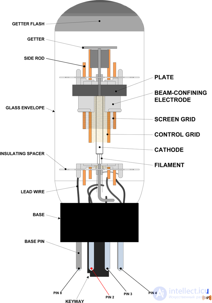
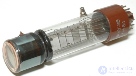
Vacuum electron devices are usually hermetically sealed glass, metal, or ceramic (nuvistor) envelopes with various electrodes inside, connected to the contacts of the device's external connector through a glass or ceramic vacuum-tight insulator. Air is first evacuated from them. The pump-down is accompanied by heating — both thermal and high-frequency (less often microwave-field) — of the device's internals in order to remove absorbed gases. A getter is also used for this purpose — a disc or ring of thin sheet metal, coated with metallic barium[citation needed for 392 days] or a special chemical compound that readily absorbs gases both during flashing and afterward. These are, as a rule, the most poisonous substances in vacuum devices.
The fewer gases remain inside, the longer-lived the device is. The minimum residual pressure in electronic devices operating at voltages up to 1 kV is considered to be 10-4 Pa for long-term operation. For high-voltage picture tubes (27 kV), the minimum is 10-7 Pa (5-10 years). For large-scale devices such as accelerators, the requirements are thousands of times higher.
Any vacuum device has a cathode (directly or indirectly heated, more rarely unheated — «cold»), often coated with a special compound for high electron emission into the vacuum of the device's working zone; and an anode — the last working electrode, which collects the «spent» electrons.
All vacuum devices use as their working substance an electron stream flying from the cathode to the anode and interacting along the way with simple electrodes (grids and focusing electrodes) and complex ones (microwave resonators, luminescent screens, etc.)
Vacuum electron devices can be divided into the following classes:
All vacuum devices use as their working substance an electron stream flying from the cathode to the anode and interacting along the way with simple electrodes (grids and focusing electrodes) and complex ones (microwave resonators, luminescent screens, etc.)
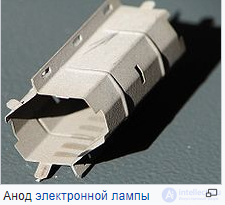
In vacuum electron devices the anode — is an electrode that attracts the flying electrons emitted by the cathode. In electron tubes and X-ray tubes the anode's construction is such that it fully absorbs the electrons. But in cathode-ray devices the anode is a component of the electron gun. It absorbs only part of the flying electrons, shaping the electron beam behind it.
In vacuum electron devices the cathode — is an electrode that is the source of free electrons, usually as a result of thermionic emission. In cathode-ray devices the cathode is part of the electron gun. To facilitate electron emission, it is, as a rule, made by depositing metals with a low electron work function and is additionally heated. Cathodes are divided into directly heated ones, where the heater filament itself is the source of electrons, and indirectly heated ones, where the cathode is heated through a ceramic insulator.
A dynode (Dynode) — is an electrode in a photomultiplier tube and some other electrovacuum devices, serving to amplify the electron stream through secondary electron emission.
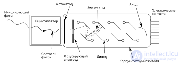
A photoelectron emitted when the cathode is illuminated is accelerated and strikes the first dynode, whose potential is 90—100 V higher than that of the cathode. Each photoelectron striking a dynode causes the emission of several electrons, which strike the second dynode, whose potential is 90—100 V higher than that of the previous one. For materials such as BeO and MgO, the number of electrons at each dynode can increase tenfold. Thus, after passing through a series of dynodes, the signal (originally 1 electron per photon of incident light) is amplified many times over.
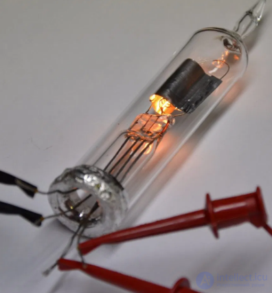
Heater filament — a coiled filament made of a refractory material (tungsten or tungsten alloys), which, owing to its resistance, converts electric current into light and heat (the heating effect of current). Used in electric and radio tubes.
The heater filament in vacuum electron devices is used to heat the cathode, in order to obtain thermionic emission of electrons from the cathode, and in some cases it is itself a directly heated cathode (for example, in vacuum fluorescent displays).
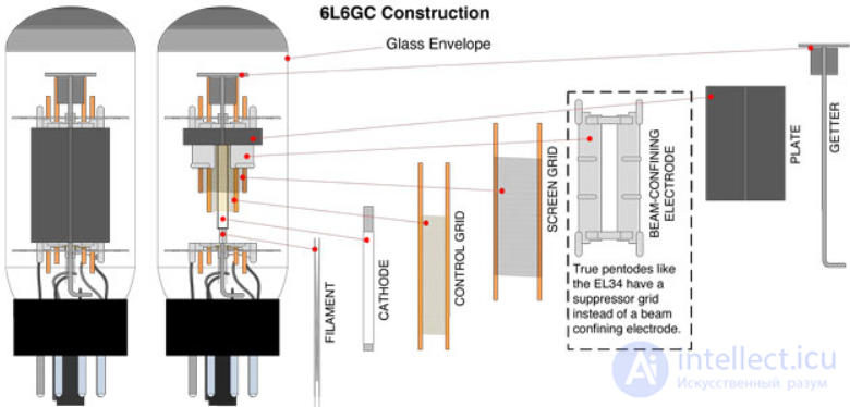
A grid — is an electrode of an electron tube, located in the electron stream between the anode and the cathode and not fully blocking it.
By purpose, grids are divided into:
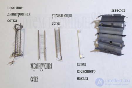
Control grid — regulates the electron stream in accordance with the input signal voltage, providing the tube's amplifying properties.
Screen grid — reduces the capacitance of the gap between the anode and the control grid, which helps prevent self-excitation, increase the amplification factor, and raise the limiting amplification frequency. Used in tetrodes, pentodes, and more complex tubes.
Suppressor grid — suppresses the dynatron effect, capturing electrons knocked out of the anode by secondary emission.
Cathode grid — in tubes with low anode voltage, for example those intended for car radio receivers powered by a 12-volt supply, is installed between the cathode and the control grid, additionally accelerating the electrons emitted by the cathode.
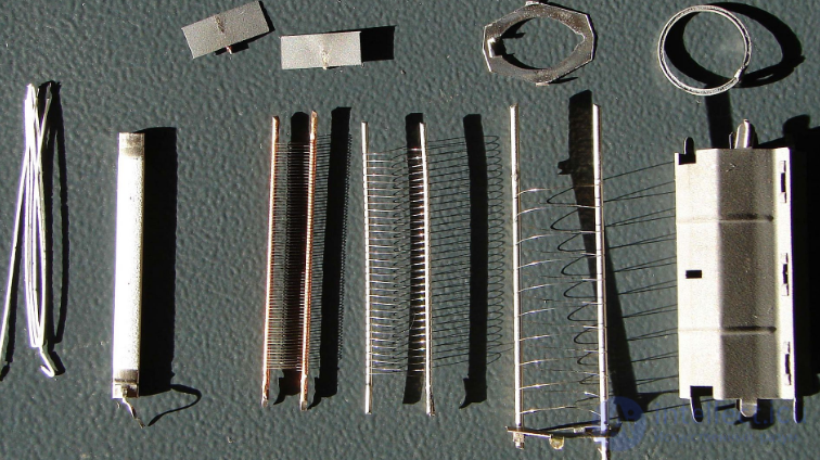
Electrodes of a pentode. In the center — three spiral grids, which in the assembled tube are nested one inside another
In some cases the purpose of the grids can be changed by the equipment designer, for example a tetrode or pentode can be used as a triode with the cathode grid, the cathode grid can be used as the control grid, the screen grid can play the role of the anode in a «virtual» triode within a tetrode or pentode (in an electron-coupled oscillator), and so on.
In the earliest tubes the grids really did look like a flat mesh woven from metal wires (hence the name); they are still used in some high-frequency tubes. Most often a grid is a sparse wire helix wound on special posts (traverses) around the cathode. A special case is rod tubes, where the role of the grids is played by pairs of thin rods running along the cathode. A system of such «grids» regulates the electron stream, not so much by retarding it as by focusing it, that is, it works like an electrostatic lens.
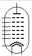
In circuit diagrams, grids are depicted as broken lines between the symbols for the cathode and the anode
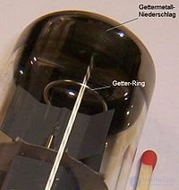
Getter in an electron tube
Getter — getter, a substance that absorbs and firmly retains gases (except inert ones), binding them through chemisorption; it is often used in devices (which in everyday usage are also called getters) for gas absorption and for providing the required degree of vacuum in electrovacuum devices and in vacuum pumps. These are, as a rule, the most poisonous substances in vacuum devices. The fewer gases remain inside, the longer-lived the device is. When residual gas interacts with electrons it becomes ionized, and the resulting positive ions bombard the cathode and other electrodes, sputtering them and «poisoning» the cathode, changing its chemical composition and coating it with a poorly emitting metal from the electrodes. And at high voltages a glow discharge ignites, short-circuiting the electrodes and greatly accelerating their wear. In addition, when amplifying weak signals, even in a well-evacuated electrovacuum device the residual gas is a strong source of noise.
The operating principle of almost all getters is based on the fact that when heated the getter metal is sputtered inside the envelope and either chemically reacts with the substances making up the residual gas, forming solid compounds, or dissolves them as a solid solution (hydrogen). In addition, during the rapid sputtering process the getter acts as a single-use vacuum pump, attracting molecules of inert gases (helium, neon) and other gases (organic compounds, ammonia) not chemically absorbed, by means of interatomic Van der Waals forces, drawing them onto the sputtered surface and «burying» them under the next layers of sputtered material that settle.
The degree of pressure reduction depends on the type of gas being evacuated. Thus, when removing air, a getter can reduce the pressure by no more than a factor of 100, since the oxygen and nitrogen of the air form oxides and nitrides with the getter metal, while argon, whose content is about 1%, almost entirely remains. But by applying a preliminary purge of the vessel being evacuated with an argon-free gas mixture, a significant increase in the degree of getter-based vacuum pumping can be achieved.
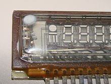
A white spot signals a breach of the indicator bulb's air-tightness
There are two main types of getters:
The maximum residual pressure in electronic devices operating at voltages up to 1 kV is considered to be 10−4 Pa for long-term operation. For high-voltage picture tubes (25 kV) the maximum is 10−7 Pa (5—10 years of operation).
In 1935—1938 so-called «red» glass tubes were developed and released (named for the color of the metallized layer on the envelope). This series of tubes was given the name of the «red» E series. It replaced the A series of tubes. Tubes of the «red» E series have a so-called pin-less base (fig. 1, panel a).
In 1938—1939 a series E with metal tubes was developed and released, having a new eight-pin base (fig. 1, panel b.) This series, which received the name of the 11th E series, replaced the «red» E series in contemporary designs.
Then so-called «keyed» tubes of the E series with a compact glass envelope were developed and released. This series was given the name of the 21st E series. It is used in modern equipment on a par with the 11th E series. These tubes have a so-called «keyed» or «loctal» base (fig. 1, panel c).
Tubes of the U series appeared in connection with the wide spread of universal-supply receivers (transformerless receivers).
Tubes of the U series were first released in 1939—1940 as the so-called 11th U series. It replaced the C series. Tubes of this series have the base shown in fig. 1, panel b.
At the same time, a fully glass-bodied so-called «red» U series was released. These tubes have an octal (American) base (fig. 1, panel d).
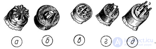
Fig. 1. Various types of bases
Pinout («pin assignment»), or lead-out wiring — a description of every contact of an electrical connection in electronic equipment, for example the pinout of radio tubes. A pinout is needed for the tasks of assembling and repairing devices containing several leads, it identifies all the contacts of the connection.
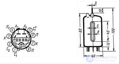
Example of the pinout of a radio tube, the GU-19
A double beam tetrode for generating, amplifying, and multiplying the frequency of high-frequency oscillations in the frequency range up to 500 MHz. Construction – glass, baseless.
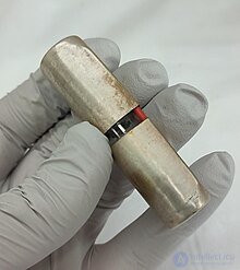
A Zellweger Zellweger glow tube containing radium-226 or tritium. There are no indicators warning of the presence of radioactive materials
Some vacuum tubes use radioactive materials to improve their performance. These radioactive materials are used to ionize the fill gas inside the tube. This ionization process ensures reliable and consistent operation, providing a steady current when a high voltage is applied, thereby improving the tube's performance and stability. The radioactive source speeds up the tube's operation and ensures that the tube's output is stable and not subject to random fluctuations, providing an instantaneous current when a high voltage is applied.
The various radioactive sources that have been used in these devices include:
Examples include the Western Electric 346B tube, containing radium-226, and the Zellweger ZE22/3 glow tube, which may contain both radium-226 and tritium.

Comments