Lecture
The main structural unit in StarUML is the project. The project is saved in a single file in XML format with the extension “.UML”. A project may contain one or several models and various representations of these models (View) - visual expressions of the information contained in the models. Each model view contains diagrams — visual images that display specific aspects of the model.
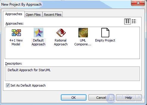
A new project will be automatically created when you start the StarUML program. In this case, you will be asked to select one of the Approaches supported by StarUML in the dialog box (see Figure 1).

Figure 1. Choosing an Approach
There are various methodologies for modeling information systems, systems companies can also develop their methodologies. Therefore, at the initial design stage it is necessary to determine the main provisions of the methodology or choose one of the existing ones. In order to reconcile the various elements and stages of modeling, StarUML proposes a concept of approaches.
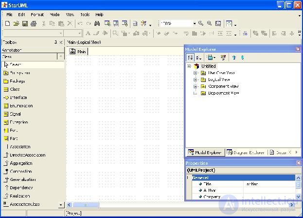
After we have chosen one of the proposed approaches, the main program window will appear (Fig. 2).
eight

Figure 2. The main program window
At the top of the window is the main menu, shortcut buttons. On the left is the Toolbox with images of chart elements. Items match the type of chart selected. In the center is the working area of the diagram, on which it can be constructed using the corresponding elements of the toolbar.
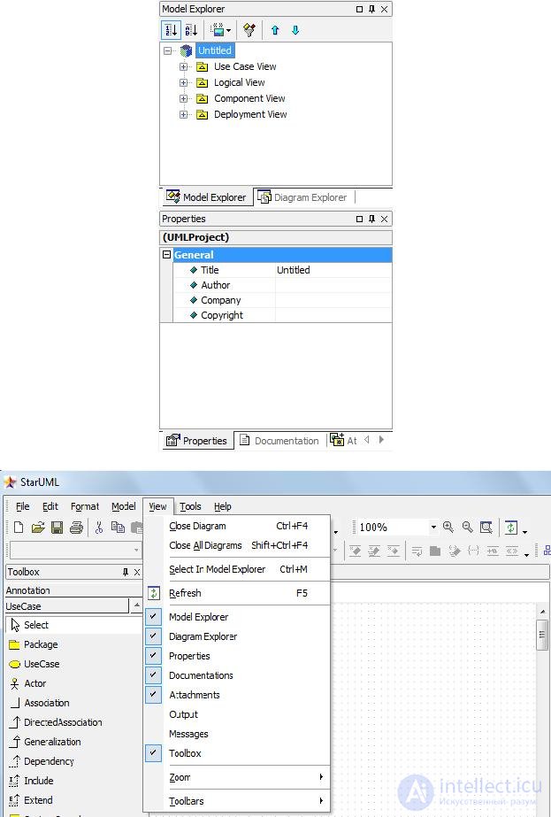
On the right is the model inspector, where you can find the tabs of the Model Exploer model navigator, the Diagram Exploer diagram navigator, the Properties properties editor window, the Documentation model elements documentation window and the Attachments attachment editor. The appearance of the tabbed inspector is shown below (Fig. 3).

Figure 3. Model inspector
Figure 4. View menu item. Management of the model inspector view
You can control the view of the model inspector, the toolbox, close and open the inspector’s editors using the View menu item (Fig.4). If there is a check mark next to the menu item, this item is active and can be seen in the program window or opened on the available tabs of the model inspector.
The hierarchical structure of the project is displayed on the right in the Model Explorer. Depending on the approach chosen, different packages of model views will be displayed on the model navigator. Each presentation package will contain the elements of the models and diagrams that we will create.
If during the creation of a new modeling project we choose the Rational Approach approach, then with this approach, four sets of system model views will be present in the navigator (see Figure 5):
• Use Case View - a view of the system requirements, describes what the system should do;
• Logical View - a logical representation of the system, describes how the system should be built;
• Component View - implementation view, describes the dependency between software components;
Deployment View is a deployment view that describes hardware elements, devices, and software components.
Figure 5. Model Navigator
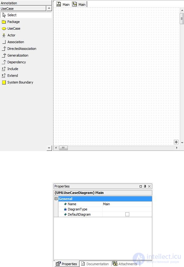
Now, each view contains one chart called Main. If you double-click on it, the working field of this diagram and the corresponding toolbar will open.
Example. If you double-click on the Main diagram of the Use Case View view, the working of this diagram and its toolbar will open.
(Fig. 6).

Figure 6. Main case use case and its toolbar
The properties of the selected model element or diagram (in this case, the properties of the Main diagram, since it is selected in the model navigator) are displayed below the hierarchy of views (see Figure 7).
Figure 7. Property Editor
Consider the visual modeling of systems using UML on the example of designing an ordering system for the Style online store.
Comments
To leave a comment
Computer Engineering Technologies
Terms: Computer Engineering Technologies