Lecture
Rectangular isometry is characterized by the fact that the distortion coefficients are 0.82. They are derived from relation (1).
For a rectangular isometry from the relation (1) we obtain:
Зu 2 = 2, or and = v - w = (2/3) 1/2 = 0.82, i.e. the segment of the coordinate axis
a length of 100 mm in a rectangular isometric representation of the axonometric axis length of 82 mm. In practical constructions it is not very convenient to use such distortion factors, therefore GOST 2.317-69 recommends using the above distortion factors:
and = v = w - 1.
The image constructed in this way will be 1.22 times the size of the object itself, i.e., the image scale in a rectangular isometry will be M A 1.22: 1.
Axonometric axes in rectangular isometry are located at an angle of 120 ° to each other (Fig. 157). The image of a circle in axonometry is of interest, especially
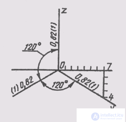
Fig. 157
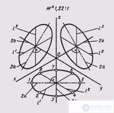
Fig. 158
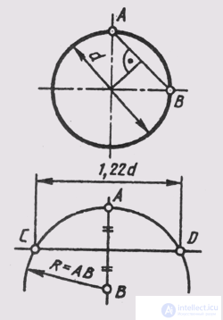
Fig. 159
but circles belonging to coordinate or parallel planes.
In the general case, a circle is projected into an ellipse if the plane of the circle is at an angle to the projection plane (see § 43). Therefore, the perspective of the circle will be an ellipse. To construct a rectangular axonometry of circles lying in coordinate or parallel planes, the rule follows: the major axis of the ellipse is perpendicular to the axonometry of that coordinate axis, which is absent in the plane of the circle.
In a rectangular isometry, equal circles located in the coordinate planes are projected into equal ellipses (Fig. 158).
The dimensions of the axes of the ellipses when using the reduced distortion coefficients are equal: the major axis 2a = 1.22d, the minor axis 2b = 0.71d, where d is the diameter of the circle being drawn.
The diameters of the circles parallel to the coordinate axes are projected by segments parallel to the isometric axes, and are represented as equal to the diameter of the circle: l 1 = l 2 = l 3 = d, while
l 1 || x; l 2 || y; l 3 || z.
An ellipse, as an isometry of a circle, can be constructed from eight points, limiting its major and minor axes and the projections of diameters parallel to the coordinate axes.
In the practice of engineering graphics, an ellipse, which is an isometry of a circle lying in the coordinate or parallel plane to it, can be replaced by a four-center oval having the same
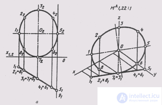
Fig. 160
Axes: 2 a = 1 , 22d and 2b = 0.71 d. In fig. 159 shows the construction of the axes of such an oval for an isometry of a circle of diameter d.
To construct axonometry of a circle located in a projecting plane or a plane of general position, it is necessary to select a certain number of points on a circle, construct an axonometry of these points and connect them with a smooth curve; get the desired ellipse — axonometric of the circle (Fig. 160).
On a circle located in a horizontally projecting plane, 8 points were taken (1,2, ... 8). The circle itself is referred to the natural coordinate system (Fig. 160, a). We draw the axes of the rectangular isometry ellipse and, using the reduced distortion coefficients, we construct a secondary projection of the circle 1 1 1 ... 160, b). Completing the axonometric coordinate polygonal lines for each of the eight points, we obtain their isometry (1 1 , 2 1 , ... 8 1 ). We combine the isometric projections of all points with a smooth curve and we obtain the isometry of a given circle.
The image of geometric surfaces in a rectangular isometry is considered on the example of constructing a standard rectangular isometry of a truncated right circular cone (Fig. 161).
The complex drawing shows a cone of rotation truncated by a horizontal level plane located at a height z from the lower base and a level profile plane giving in
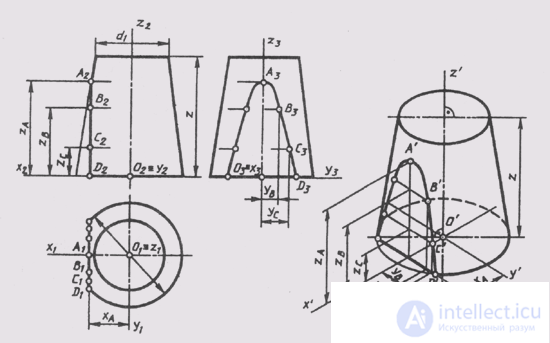
Fig. 161
hyperbola with vertex at point A. Projections of the hyperbola are constructed by its separate points.
We assign the cone to the natural coordinate system Oxyz. We construct the projections of the natural axes on the complex drawing and separately their isometric projection. The construction of an isometry begins with the construction of ellipses of the upper and lower bases, which are isometric projections of the circles of the bases. Small axes of ellipses coincide with the direction of the isometric axis O Z (see. Fig. 158). Large axes of ellipses are perpendicular to small ones. The magnitudes of the axis ellipses are determined depending on the diameter of the circle (d is the lower base and d 1 is the upper base). Then build an isometric section of the conical surface of the profile plane of the level, which intersects the base in a straight line, separated from the origin by X A and parallel to the axis O y .
The isometry of the hyperbola points is plotted according to the coordinates measured on the complex drawing, and set aside along the corresponding isometric axes, since the reduced distortion coefficients and = v = w = 1. We combine the isometric projections of the hyperbola points with a smooth curve. The construction of the image of a cone ends with an essay forming tangent to the ellipses of the bases. The invisible part of the ellipse of the lower base is drawn by a dashed line.

Comments
To leave a comment
12. Axonometric projections
Terms: 12. Axonometric projections