This example shows the I-V characteristic of a diode. With a resistor, I (current) and V (voltage) are proportional (by Ohm's law). In the case of a diode, I and V have an exponential relationship. At the bottom left, voltage is displayed in green and current in yellow. In the lower right corner is a graph of current versus voltage (the I/V curve).
This page is a utility for simulating график вах диода online with specified initial values.
The diode I-V characteristic (current-voltage characteristic) is simply a graph that shows how current flows through a diode at different voltages.
Horizontally — voltage (U)
Vertically — current (I)
When the diode is connected «correctly»:
At first almost no current flows
Then there is a «threshold» (about 0.6–0.7 V for silicon diodes)
After this the current rises sharply
That is, the diode begins to conduct current well only after a certain voltage.
When the diode is connected the other way around:
Almost no current flows at all
There is only a very small leakage
The diode is as if «closed»
If you strongly increase the reverse voltage
The diode can «break down»
Current will surge (and the diode may be destroyed)
A diode is like a valve:
In one direction it lets flow through (but not immediately)
In the other — it almost does not let anything through
The diode I-V characteristic shows:
where it is closed
where it begins to conduct
where it can break down
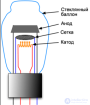
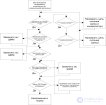
For practical purposes, the operating modes of a diode must be described by quantities and characteristics that are set and measured using external sources and instruments. Such quantities are the filament voltage UH and current IH, the anode voltage Ua and current Ia, as well as the geometric parameters of the electrodes.
The main practical characteristic of diode operation is the current-voltage characteristic (I-V characteristic) — the dependence of the anode current on the anode-cathode voltage Ia=f(Ua).
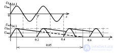
Since the specific shape of the I-V characteristic depends on the filament current, diode operation is described by a family of I-V characteristics 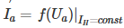 .
.
The figure shows a family and a single I-V characteristic of a diode. The negative anode voltage mode (I) is called the retarding potential mode.
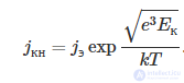
To a first approximation, it can be assumed that in this region the dependence of current on voltage is exponential in nature
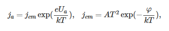 ,
,
and is determined by the Maxwellian velocity distribution of the electrons. This mode is used in laboratory work 2.3.
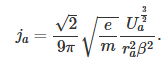
The «three-halves law» mode - region II.
In the «three-halves» mode, in accordance with the Bogoslovsky–Langmuir formula, the dependence of the current density at the cathode on the anode voltage () has the form:
for flat electrodes (the Child–Langmuir formula, derivation of the formula problem 3.32 from the Collection of Problems in Electrodynamics Batygin V.V., Toptygin I.N., RCD, 2002.)
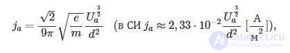
It can be assumed that in this region the dependence of the anode current density on the anode voltage is described by the formula
The regions of modes I and II are separated by a transition-mode region I', in which the influence of the contact potential difference and the potential barrier in the diode gap, arising due to the initial thermal velocities of the electrons (at zero external cathode–anode voltage), leads to deviations from the calculated formulas.
The Schottky effect mode (region III) is also separated from the three-halves mode by a transition region II', in which the non-uniformity of the temperature and work function over the cathode surface manifests itself.
In region III the anode current is equal to the emission current Ia=Iem and its dependence on the anode voltage (on the field strength near the cathode) is described by the formula
 .
.


Comments