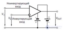
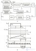
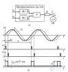
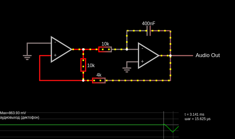
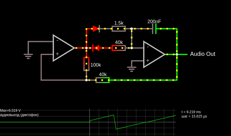
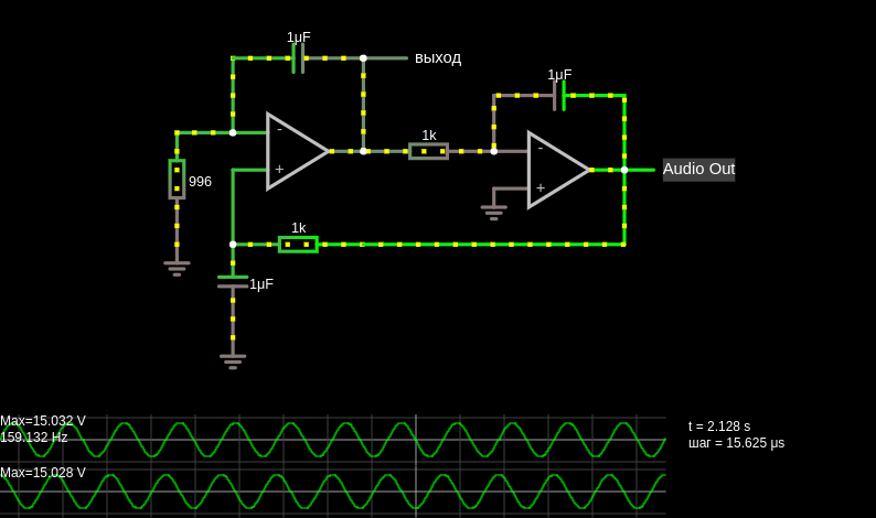
This circuit is a voltage-controlled oscillator, which is an oscillator whose frequency is determined by a control voltage. In this case, the control voltage is provided by a 10 Hz sawtooth generator; this causes the frequency to slowly rise until it reaches a maximum, then it returns to the starting frequency. The first op-amp is an integrator. The voltage divider sets the + input at half the control voltage. The op-amp tries to keep the same voltage at its inputs, which requires current to flow through the 100 kΩ to ensure that its voltage drop is half the control voltage. When the MOSFET at the bottom is on, the current from the 100 kΩ flows through the MOSFET. Since the 49.9 kΩ resistor has the same voltage drop as the 100 kΩ resistor but half the resistance, twice as much current must flow through it. The additional current comes from the capacitor charging it, so the first op-amp must provide a continuously rising output voltage to source this current. When the MOSFET at the bottom is off, the current from the 100 kΩ flows through the capacitor, discharging it, so a continuously falling output voltage from the first op-amp is needed. The third area shows the output voltage; it resembles a triangle wave. The second op-amp is a Schmitt trigger. It uses the triangle wave as its input. When the input voltage rises above the 3.33 V threshold, it outputs 5 V, and the threshold voltage falls to 1.67 V. When the input voltage falls below this value, the output voltage becomes 0 V, and the threshold increases again. The output is a square wave. It is connected to the MOSFET, causing the integrator to raise or lower its output voltage as needed. To hear the signal, increase the simulation speed and press the Play button.
This page is a utility for simulating voltage-controlled oscillator (vco) online with specified initial values.

Comments