
Lecture 35 min.
A programmable logic controller (abbr. PLC; a more precise rendering is "controller with programmable logic"), or programmable controller, is a special kind of electronic computer. PLCs are most often used to automate technological processes. The main mode of operation of a PLC is long-term autonomous use, often in unfavorable environmental conditions, without major maintenance and with practically no human intervention.
Sometimes computer numerical control (CNC) systems for machine tools are built on PLCs.
PLCs are devices designed to operate in real-time systems.
PLCs have a number of features that distinguish them from other electronic devices used in industry:
In control systems for technological objects, logical instructions, as a rule, predominate over arithmetic operations on floating-point numbers, which makes it possible, with the relative simplicity of a microcontroller (8- or 16-bit buses), to obtain powerful systems operating in real time. In modern PLCs, numerical operations are implemented in their programming languages on a par with logical ones. All PLC programming languages give easy access to bit manipulation in machine words, unlike most high-level programming languages of modern computers.
The first logic controllers appeared in the form of cabinets with a set of interconnected relays and contacts. This circuit could not be changed after the design stage and was therefore called hard-wired logic. The world's first programmable logic controller, in 1968, was the Modicon 084 (1968) (from "modular digital controller"), which had 4 KB of memory.
The term PLC was introduced by Odo Josef Struger (Allen-Bradley) in 1971. He also played a key role in unifying PLC programming languages and adopting the IEC 61131-3 standard. Together with Richard Morley (Modicon), they are called the "fathers of the PLC". Alongside the term PLC, the term microprocessor-based command device was widely used in the 1970s.
In the first PLCs, which replaced relay logic controllers, the operating logic was programmed using an LD (ladder diagram) wiring scheme. The device had the same principle of operation, but the relays and contacts (other than the input and output ones) were virtual, that is, they existed in the form of a program executed by the PLC's microcontroller. Modern PLCs are freely programmable.
PLCs emerged in the late 1960s in the U.S. automotive industry and were developed to replace relay logic systems. Previously, the control logic for manufacturing consisted mainly of relays, cam timers, drum sequencers and dedicated closed-loop controllers.
The hard-wired nature hindered design engineers from changing the process. Changes would require rewiring and careful updating of the documentation. If even one wire was out of place or one relay failed, the entire system would fail. Technicians often spent hours troubleshooting, examining diagrams and comparing them with the existing wiring. When general-purpose computers became available, they were soon applied to controlling the logic of industrial processes. These early computers were unreliable and required specialist programmers and strict control of operating conditions such as temperature, cleanliness and power quality.
The PLC offered several advantages over earlier automation systems. It tolerated the industrial environment better than computers, was more reliable and compact, and required less maintenance than relay systems. It could be easily expanded with additional input/output modules, whereas relay systems required complex hardware changes when reconfigured. This made it easier to iterate on the design of a production process. Thanks to a simple programming language focused on logic and switching operations, it was more user-friendly than computers using general-purpose programming languages. It also made it possible to monitor its operation. Early PLCs were programmed in ladder logic, which closely resembled a schematic diagram of relay logic. This program notation was chosen to reduce the need for training existing technicians. Other PLCs used a form of instruction list programming based on a stack-based logic solver.
In 1968, GM Hydramatic (the automatic transmission division of General Motors) issued a request for proposals for an electronic replacement for hard-wired relay systems, based on a white paper written by engineer Edward R. Clark. The winning proposal came from Bedford Associates of Bedford, Massachusetts. The result was the first PLC, built in 1969 and designated 084 because it was Bedford Associates' eighty-fourth project.
Bedford Associates founded a company to develop, manufacture, sell and service this new product, which they called Modicon (meaning modular digital controller). One of the people who worked on this project was Dick Morley, who is considered the "father" of the PLC. The Modicon brand was sold in 1977 to Gould Electronics, and later to Schneider Electric, the current owner.
One of the first 084 models built is now on display at the Schneider Electric facility in North Andover, Massachusetts. It was given back to Modicon by GM when the unit was decommissioned after almost twenty years of continuous service. Modicon used the nickname 84 at the end of its product range until the 984 model appeared.
In a parallel development, Odo Josef Struger is also sometimes called the "father of the programmable logic controller". He took part in inventing the Allen-Bradley programmable logic controller between 1958 and 1960 and is credited with coining the acronym PLC. Allen-Bradley (now a brand owned by Rockwell Automation) became a major PLC manufacturer in the United States during his tenure. Struger played a leading role in developing the IEC 61131-3 PLC programming language standards.
Many early PLCs could not represent logic graphically, so it was instead represented as a series of logical expressions in some Boolean format, similar to Boolean algebra. As programming terminals evolved, it became more common to use ladder logic, since it was a familiar format used for electromechanical control panels. Newer formats exist, such as state logic and function block (which is similar to the way logic is displayed when using digital integrated logic circuits), but they are still not as popular as ladder logic. The main reason for this is that PLCs solve the logic in a predictable and repeating sequence, and ladder logic allows the person writing the logic to see any problems with the timing of the logic sequence more easily than would be possible in other formats
Until the mid-1990s, PLCs were programmed using proprietary programming panels or dedicated programming terminals, which often had special function keys representing the various logical elements of PLC programs. Some proprietary programming terminals displayed the elements of PLC programs as graphic symbols, but plain ASCII characters represented contacts, coils and wires. Programs were stored on cassette tapes. Printing and documentation capabilities were minimal because of a lack of memory. The oldest PLCs used non-volatile magnetic core memory.
It is precisely this direction that has been developing considerably in recent times, and this is due to certain reasons. These reasons are:
These controllers are used to control small self-contained objects in industry, in specialized automation systems in medicine and in other areas. The controller performs functions that involve complex processing of measurement information with the calculation of several control actions, while the total number of inputs/outputs does not exceed a few dozen. The main advantages of these controllers are a large volume of computation in a fairly short period of time, similarity to the operating conditions of office PCs, and the possibility of programming in a high-level language. Hardware support is provided by ordinary controllers with functions of in-depth diagnostics and fault elimination without stopping the controller's operation.
A local programmable controller (LPC) is subject to the following classification:
These controllers have medium computing capability, i.e., power. It is a comprehensive characteristic that depends on the frequency and word length of the computer and on the amount of RAM. To exchange information with other automation systems, local controllers have several physical ports. These controllers implement typical functions of measurement information processing, interlocking, regulation and programmed logic control. Emergency protection systems use a special type of local controller, since these are distinguished by high reliability, survivability and speed. They also provide full fault diagnostics with fault localization, and redundancy of components and of the device as a whole.
A PLC often consists of the following parts:
Usually, an input or output of a PLC cannot be connected directly to the corresponding output of the central chip. These outputs are characterized by low voltage levels, usually from 3.3 to 5 volts. PLC inputs and outputs usually have to work with voltages of 24 V DC or 220 V AC. Therefore, amplifying and protective elements must be provided between the PLC output and the chip output.
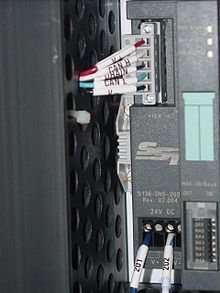
A PLC is an industrial microprocessor-based controller with programmable memory used to store program instructions and various functions. It consists of:
A PLC requires a programming device, which is used to develop the program and then load it into the controller's memory.
Modern PLCs usually contain a real-time operating system such as OS-9 or VxWorks.
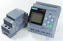
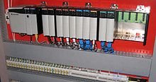
There are two types of mechanical design for PLC systems. A single box, or brick, is a small programmable controller that fits all its components and interfaces in one compact enclosure, although additional expansion modules for inputs and outputs are usually available. The second type of design, the modular PLC, has a chassis (also called a rack) that provides space for modules with various functions, such as a power supply, a processor, a selection of I/O modules and communication interfaces, all of which can be configured for a specific application. [19]Several racks can be managed by a single processor and can have thousands of inputs and outputs. Either a special high-speed serial I/O link or a comparable communication method is used, so that racks can be distributed separately from the processor, which reduces wiring costs for large plants. Options are also available for mounting I/O points directly on the machine and using quick-disconnect cables for sensors and valves, which saves time on wiring and component replacement.
Discrete (digital) signals can take only on or off values (1 or 0, true or false ). Examples of devices that provide a discrete signal include limit switches , photoelectric sensors and encoders . [20] Discrete signals are sent using either voltage or current , where specific extreme ranges are designated as on and off . For example, a controller might use a 24 V DC input, with values above 22 V DC representing o n , values below 2 V DC representing o ff., and intermediate values undefined.
Analog signals can use voltage or current that is proportional to the size of the monitored variable and can take any value within their scale. Pressure, temperature, flow and weight are often represented by analog signals. They are usually interpreted as integers with various ranges of accuracy, depending on the device and the number of bits available to store the data. [20] For example, an analog input of 0 to 10 V or 4-20 mA will be converted into an integer value from 0 to 32,767. The PLC will accept this value and scale it into the required process units so that an operator or a program can read it. Proper integration will also include filtering time to reduce noise, as well as high and low limits for reporting faults. [21] Current inputs are less sensitive to electrical noise (for example, from welders or electric motor starts) than voltage inputs. The distance between the device and the controller is also a concern, since the maximum distance a good-quality 0–10 V signal can travel is very short compared with a 4–20 mA signal. A 4-20 mA signal can also indicate if a wire has been disconnected along the way, since it then returns a 0 mA signal.
Some special processes need to run continuously with a minimum of unwanted downtime. Therefore, it is necessary to design a fault-tolerant system that can handle the process with failed modules. In such cases, to increase system availability in the event of a hardware component failure, redundant CPU or I/O modules with the same functionality can be added to the hardware configuration to prevent a full or partial process shutdown caused by a hardware failure. Other redundancy scenarios may involve safety-critical processes; for example, large hydraulic presses may require both PLCs to turn on an output before the press can stroke, in case one output fails to turn off properly.
PLCs are programmed using the standardized IEC languages of the IEC 61131-3 standard
Programming languages (graphical)
Programming languages (textual)
Structurally, in IEC 61131-3 the execution environment is a set of resources (in most cases this is the PLC itself, although some powerful computers running multitasking operating systems make it possible to run several softPLC-type programs and emulate several resources on a single CPU). A resource provides the ability to execute tasks. Tasks consist of a set of programs. Tasks can be invoked cyclically, on an event, or at the maximum frequency.
A program is one of the types of program organization units (POU). POUs can be of the program, function block and function types. In some cases, non-standard languages are used to program PLCs, for example: algorithm flowcharts, a C-oriented development environment for PLC programs, and HiGraph 7, a control language based on system state graphs.
Tools for programming PLCs in the IEC 61131-3 languages may be specialized for a particular PLC family or universal, working with several (but by no means all) types of controllers:
Programmable logic controllers are designed to be used by engineers without programming experience. For this reason, a graphical programming language called Ladder Diagram (LD, LAD) was developed first. It resembles the schematic diagram of a system built with electromechanical relays, and it was adopted by many manufacturers and later standardized in the IEC 61131-3 control systems programming standard . As of 2015, it is still widely used because of its simplicity.
As of 2015, most PLC systems conform to the IEC 61131-3 standard, which defines 2 textual programming languages: Structured Text (ST; similar to Pascal ) and Instruction List (IL); as well as 3 graphical languages: ladder diagram , function block diagram (FBD) and sequential function chart (SFC). Instruction List (IL) was declared deprecated in the third edition of the standard.
Modern PLCs can be programmed in a variety of forms, from the relay-derived ladder logic to programming languages such as specially adapted dialects of BASIC and C .
Although the fundamental concepts of PLC programming are common to all manufacturers, differences in I/O addressing, memory organization and instruction sets mean that PLC programs can never be completely interchangeable between different manufacturers. Even within the same product line of one manufacturer, different models may not be directly compatible
PLC programming differs from traditional programming. This is because PLCs execute an endless sequence of program cycles, in each of which:
Therefore, PLC programming uses flags — Boolean variables indicating that the program algorithm has passed through particular branches of conditional jumps. Hence, PLC programming requires a certain skill from the programmer.
For example, consider the initialization procedures of the system after a reset or power-up. These procedures need to be executed only once. Therefore, a Boolean variable (flag) of initialization completion is introduced, which is set when initialization finishes. The program checks this flag, and if it is set, it bypasses the execution of the initialization code.
PLC programs are usually written on a programming device, which can take the form of a desktop console, special software on a personal computer, or a handheld programming device . The program is then downloaded to the PLC directly or over a network. It is stored either in non-volatile flash memory or in battery-backed RAM . In some programmable controllers, the program is transferred from a personal computer to the PLC through a programming board that writes the program to a removable chip such as an EPROM .
Manufacturers develop software for programming their controllers. In addition to the ability to program PLCs in several languages, they provide common functions such as hardware diagnostics and maintenance, software debugging and offline simulation.
A program written on a personal computer, or uploaded from the PLC using the programming software, can easily be copied and backed up to external storage.
PLC simulation is a feature often found in PLC software. It allows testing and debugging early in a project's development.
An incorrectly programmed PLC can lead to reduced productivity and dangerous situations. Testing the project in simulation improves its quality, increases the level of equipment-related safety, and can save costly downtime during the installation and commissioning of automated control applications, since many scenarios can be tried out and tested before the system is activated.
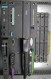
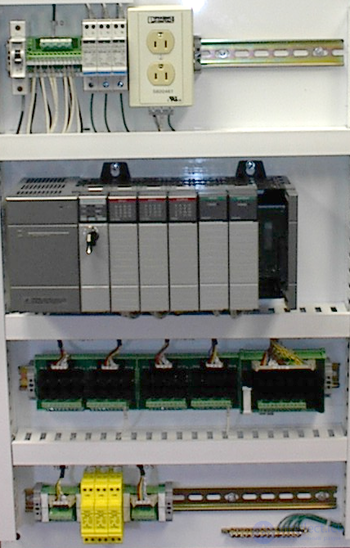
The main difference from most other computing devices is that PLCs are designed for operation in harsher environments (for example, dust, humidity, heat, cold) and are therefore resistant to them, and that they offer extensive input/output (I/O) for connecting the PLC to sensors and actuators . PLC inputs can include simple digital elements such as limit switches , analog variables from process sensors (for example, temperature and pressure), and more complex data such as data from positioning systems or machine vision . [27] PLC outputs can include elements such as indicator lamps, sirens, electric motors , pneumatic or hydraulic cylinders, magnetic relays , solenoids or analog outputs. The I/O devices may be built into a simple PLC, or the PLC may have external I/O modules connected to an industrial bus or a computer network that connects to the PLC.
The functionality of PLCs has evolved over the years and includes sequential relay control, motion control, process control , distributed control systems and networking. The data handling, storage, processing power and communication capabilities of some modern PLCs are roughly equivalent to those of desktop computers. PLC-like programming combined with remote I/O hardware allows a general-purpose desktop computer to overlap with some PLCs in certain applications. Desktop computer controllers have not been widely accepted in heavy industry because desktop computers run on less stable operating systems than PLCs, and because desktop computer hardware is typically not rated for the same levels of temperature, humidity and vibration tolerance and durability as the processors used in PLCs. Operating systems such as Windows do not lend themselves to the execution of deterministic logic, so the controller cannot always respond to changes in input state with the timing consistency expected from a PLC. Desktop logic applications find use in less critical situations,
The basic function of a programmable controller is to emulate the functions of electromechanical relays. Discrete inputs are given a unique address, and a PLC instruction can test whether the input state is on or not. Just as a series of relay contacts performs a logical AND function, not allowing current to pass until all the contacts are closed, so a series of "check if on" instructions activates its output storage bit if all the input bits are on. Similarly, a parallel set of instructions will perform a logical OR. In an electromechanical relay wiring diagram, a group of contacts controlling one coil is called a "rung" of a "ladder diagram", and this concept is also used to describe PLC logic. Some PLC models limit the number of series and parallel instructions in one "rung" of logic. The output of each rung sets or clears a memory bit, which may be associated with a physical output address or which may be an "internal coil" with no physical connection. Such internal coils can be used, for example, as a common element in several separate rungs. Unlike physical relays, there is usually no limit to the number of references to an input, output or internal coil in a PLC program.
Some PLCs enforce a strict left-to-right, top-to-bottom order of execution for evaluating the rung logic. This differs from electromechanical relay contacts, which, in a sufficiently complex circuit, can pass current either from left to right or from right to left, depending on the configuration of the surrounding contacts. The elimination of these "sneak paths" is either a bug or a feature, depending on the programming style.
More advanced PLC instructions may be implemented as function blocks, which perform some operations when enabled by a logical input and which produce output signals to indicate, for example, completion or errors, while internally manipulating variables that may not correspond to discrete logic.
PLCs use built-in ports such as USB , Ethernet , RS-232 , RS-485 or RS-422 to communicate with external devices (sensors, actuators) and systems (programming software, SCADA , HMI ). Communication takes place over various industrial network protocols such as Modbus or EtherNet/IP . Many of these protocols are manufacturer-specific.
PLCs used in larger I/O systems may have peer-to-peer (P2P) communication between processors. This allows individual parts of a complex process to have individual control while allowing the subsystems to coordinate over the communication link. These communication links are also often used for HMI devices such as keypads or PC-type workstations .
In the past, some manufacturers offered dedicated communication modules as an option when the processor had no built-in network connectivity.
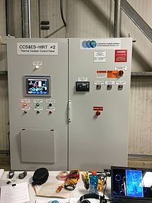
A PLC may need to interact with people for the purpose of configuration, alarm reporting or everyday control. A human-machine interface (HMI) is used for this. HMIs are also called man-machine interfaces (MMI) and graphical user interfaces (GUI). A simple system may use buttons and indicators to interact with the user. Text displays are available, as well as graphical touch screens. More complex systems use programming and monitoring software installed on a computer, with the PLC connected through a communication interface.
A PLC operates in a program scan cycle, in which it executes its program repeatedly. The simplest scan cycle consists of 3 steps:
The program follows a sequence of instructions. It typically takes the processor several tens of milliseconds to evaluate all the instructions and update the state of all the outputs. If the system contains remote I/O - for example, an external rack with I/O modules - this introduces additional uncertainty into the response time of the PLC system.
As PLCs became more advanced, methods were developed to change the sequence of ladder logic execution, and subroutines were implemented. This advanced programming can be used to save scan time for high-speed processes; for example, parts of the program used only for setting up the machine can be separated from those required for operation at higher speed. Newer PLCs now have the ability to run the logic program synchronously with the I/O scan. This means that I/O operations are updated in the background, and the logic reads and writes values as needed during the logic scan.
Special-purpose I/O modules may be used where the PLC scan time is too long to allow predictable performance. Precision timing modules or counter modules for use with shaft encoders are used where the scan time would be too long to reliably count pulses or detect the direction of encoder rotation. This allows even a relatively slow PLC to still interpret the counted values to control the machine, since the accumulation of pulses is done by a dedicated module that is not affected by the speed of program execution.
In his 1998 book, E. A. Parr pointed out that although most programmable controllers require physical keys and passwords, the lack of strict access control and version control systems, together with an easy-to-understand programming language, make it likely that unauthorized changes to programs will occur and go unnoticed.
Until the discovery of the Stuxnet computer worm in June 2010, little attention was paid to PLC security. Modern programmable controllers generally contain real-time operating systems, which can be vulnerable to exploits in the same way as desktop operating systems such as Microsoft Windows . PLCs can also be attacked by gaining control of a computer they communicate with. Since 2011, this concern has been growing as networks become more common in PLC environments, connecting previously separate production and office networks. [33]
In recent years, "safety" PLCs have become popular, either as standalone models or as functional and safety hardware added to existing controller architectures ( Allen-Bradley GuardLogix, Siemens F-series, etc.). They differ from conventional PLC types in that they are suitable for safety-critical applications, for which PLCs have traditionally been supplemented with hard-wired safety relays and areas of memory dedicated to safety instructions. The safety level standard is SIL . For example, a safety PLC might be used to control access to a robotic cell with trapped-key access, or perhaps to control the shutdown response to an emergency stop on a conveyor production line. Such PLCs typically have a restricted set of regular instructions, supplemented by safety instructions designed to interface with emergency stops, light curtains and so on. The flexibility such systems offer has led to a rapid growth in demand for these controllers.

PLCs are well adapted to a range of automation tasks. These are typically industrial processes in manufacturing where the cost of developing and maintaining the automation system is high relative to the total cost of the automation, and where changes can be expected over the lifetime of the system. PLCs contain input and output devices compatible with industrial pilot devices and controls; little electrical design is required, and the design problem centers on expressing the desired sequence of operations. PLC applications are typically highly specialized systems, so the cost of a packaged PLC is low compared with the cost of a specific custom-built controller design. On the other hand, in the case of mass-produced goods, customized control systems are economical. This is due to the lower cost of components, which can be chosen optimally instead of a "generic" solution,
Programmable controllers are widely used for motion, positioning or torque control. Some manufacturers produce motion control units that integrate with PLCs so that G-code (including CNC machines ) can be used to control machine motions.
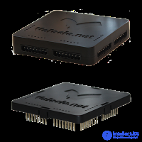
For small machines with small or medium volume. PLCs that can execute PLC languages such as Ladder, Flow-Chart / Grafcet and so on, in a language that is easy to use, modify and maintain. This sits between the classic PLC / Micro-PLC and microcontrollers.
For high volumes or very simple fixed automation tasks, different methods are used. For example, a cheap household dishwasher will be controlled by an electromechanical cam timer costing only a few dollars to produce.
A microcontroller-based design would be appropriate where hundreds or thousands of units will be produced, and so the development cost (designing power supplies, I/O hardware, and the need for testing and certification) can be spread over many sales, and where the end user does not need to change the control. Automotive applications are an example; millions of units are produced each year, and very few end users modify the programming of these controllers. However, in some specialized vehicles, such as transit buses, it is economical to use PLCs instead of custom-designed controls, because the volumes are low and the development cost would be uneconomical.
Very complex process control, such as that used in the chemical industry, may require algorithms and performance beyond the capability of even high-performance PLCs. Very fast or precise control may also require custom solutions; for example, aircraft flight controls. Single-board computers using semi-custom or fully proprietary hardware may be chosen for very demanding control applications where high development and maintenance costs can be supported. "Soft PLCs" running on desktop computers can interface with industrial I/O hardware while executing programs in a version of a commercial operating system adapted for process control needs.
The growing popularity of single-board computers has also influenced the development of PLCs. Traditional PLCs are usually closed platforms, but some newer PLCs (for example the ctrlX from Bosch Rexroth, the PFC200 from Wago, the PLCnext from Phoenix Contact, and the Revolution Pi from Kunbus) provide the functionality of a traditional PLC on an open platform.
PLCs can include logic for a single-variable analog closed-loop control circuit, a PID controller. A PID loop can be used, for example, to control the temperature of a manufacturing process. Historically, PLCs were usually configured with only a few analog control loops; where processes require hundreds or thousands of loops, a distributed control system (DCS) would be used instead. As PLCs became more powerful, the boundary between DCS and PLC applications became blurred.
In more recent years, small products called programmable logic relays (PLRs) or smart relays have become more common and accepted. They are similar to PLCs and are used in light industry where only a few I/O points are required and low cost is desirable. These small devices generally share a common physical size and shape across several manufacturers, and are rebranded by the makers of larger PLCs to fill out their low-end product range. Most of them have from 8 to 12 discrete inputs, from 4 to 8 discrete outputs, and up to 2 analog inputs. Most such devices include a tiny, postage-stamp-sized LCD screen for viewing simplified ladder logic (only a very small part of the program is visible at any one time) and the status of the I/O points, and these screens are usually accompanied by a 4-way rocker button plus four more separate buttons, similar to the buttons on a VCR remote control, which are used to navigate and edit the logic. Most of them have a small connector for connecting via RS-232 or RS-485 to a personal computer, so that programmers can use simple Windows applications for programming instead of being forced to use the tiny LCD and set of buttons for this purpose. Unlike regular PLCs, which are usually modular and greatly expandable, PLRs are usually neither modular nor expandable, but their price can be two orders of magnitude lower than that of a PLC, and they still offer robust design and deterministic execution of logic.
A variant of PLCs used in remote locations is the remote terminal unit, or RTU. An RTU is typically a ruggedized, low-power PLC whose key function is to manage the communication links between the site and a central control system (usually SCADA) or, in some modern systems, the "Cloud". Unlike factory automation, which uses high-speed Ethernet, communication links to remote sites are often radio-based and less reliable. To allow for the reduced reliability, an RTU will buffer messages or switch to alternative communication paths. When buffering messages, the RTU timestamps each message so that the full history of site events can be reconstructed. RTUs, being PLCs, have a wide range of inputs/outputs and are fully programmable, usually with languages from the IEC 61131-3 standard, which is common to many PLCs, RTUs and DCSs. In remote locations it is common to use an RTU as a gateway for a PLC, where the PLC performs all the control of the site and the RTU manages communications, timestamping of events and monitoring of auxiliary equipment. At sites with a small number of I/O operations, the RTU may also be the site PLC and perform both communication and control functions.

Comments