Lecture
Plate antenna amplifiers are designed to increase the signal level and compensate for losses in the transmission lines. Approximately the same design allows their use in various designs of broadband antennas. Such amplifiers are manufactured using SMD technology using the most advanced low-noise transistors, which are manufactured by leading foreign companies - ITT, Siemens, Philips, etc. Due to the fully automated multiple control plate amplifiers have good reliability, and due to the protective coating, they are resistant to atmospheric effects.
Currently, the largest assortment consists of plate-type amplifiers SWA, WS, RA, RAE, GPS, etc. They have different circuit solutions, which makes it possible to achieve the desired results in areas with different levels of the received signal by the simplest selection.
In areas with a relatively good received signal level, amplifiers with a single amplification stage (single stage) SWA-1, SWA-1 / LUX, PA-2, S & A-110 are usually used.
In areas with insufficient received signal, two-stage (two-stage) amplifiers WS-2, SWA-3, SWA-4 / LUX, SWA-5 (SWA-6), SWA-7, SWA-8, SWA-9, PA are used. 5, S & A-130, PA-9, S & A-140, PA-10, S & A-120, PAE-14, PAE-42, RAE-43, PAE-44, RAE-45, PAE-65, PAE-65TS, WA-031, WA-032, WA-041, WA-042, WA501S-1.
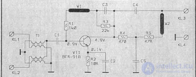
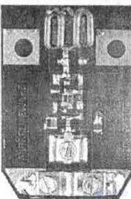
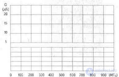
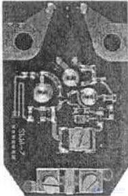
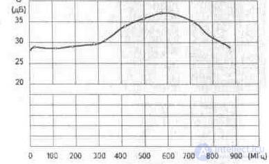
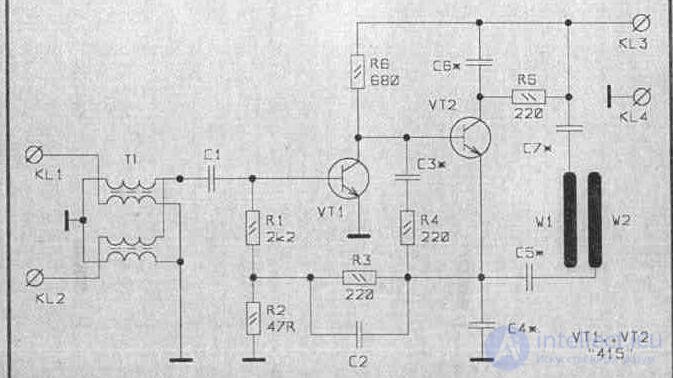
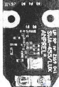
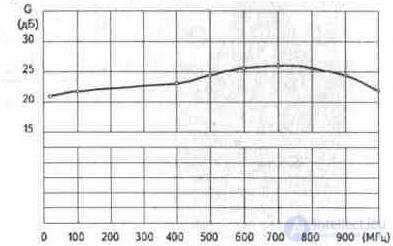
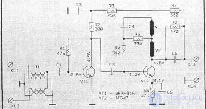
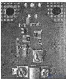
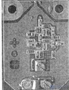
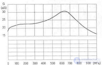
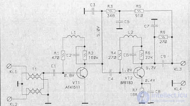
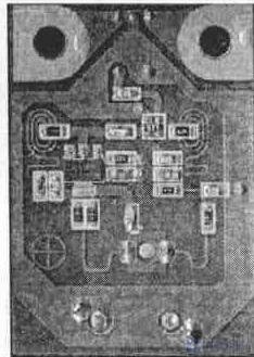
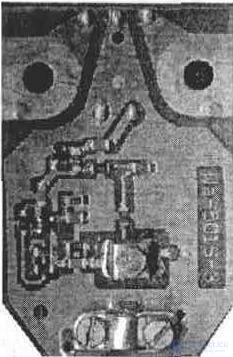
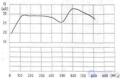
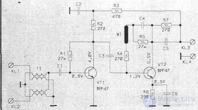
Below are the technical specifications and their schematic diagrams of the above amplifiers, as well as their appearance.
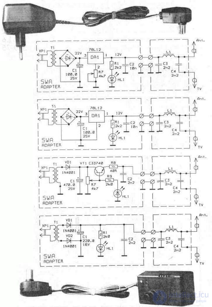
The voltage supply to the plate amplifiers is carried out by adapters that differ only in the design of the case. The main schematics of power supplies are shown on page 115.
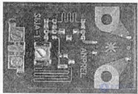
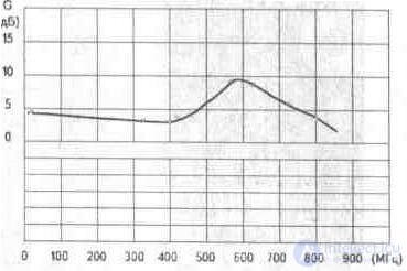
SWA-1
Reception channels 1 - 68
Gain (G), dB 8 ... 10
Noise ratio (F), dB 2, 5
Input / output resistance, Ohm 300/75
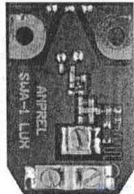
SWA-1 LUX
Reception channels 1 - 68
Gain (G), dB 15 ... 18
Noise ratio (F), dB 0, 9
Input / output resistance, Ohm 300/75
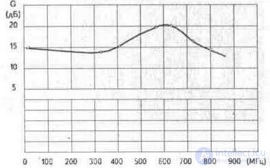
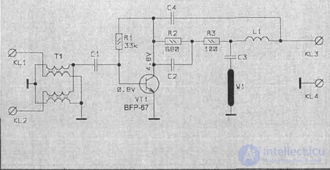
PA-2
Receive band, MHz 40 ... 800
Gain (C), dB 12
Noise ratio (P), dB 3, 5
Input / output resistance, Ohm 300/75
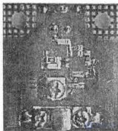
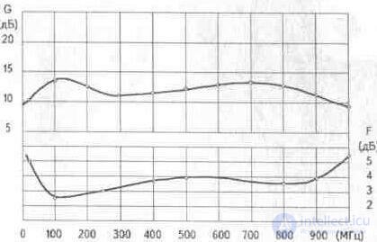
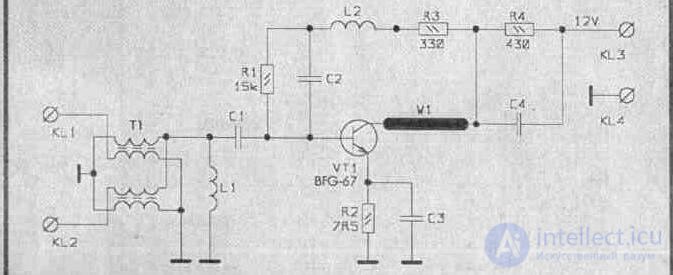
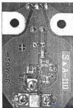
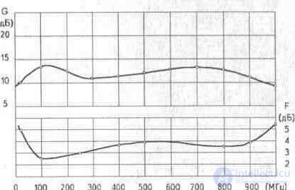
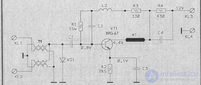
S & A-110
Receive band, MHz 40 ... 800
Gain (G), dB 12
Noise ratio (F), dB 3, 5
Input / output resistance, Ohm 300. 75
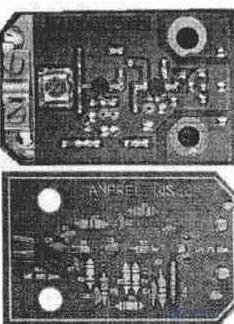
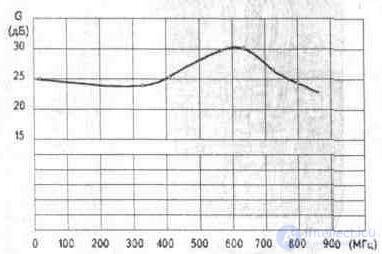
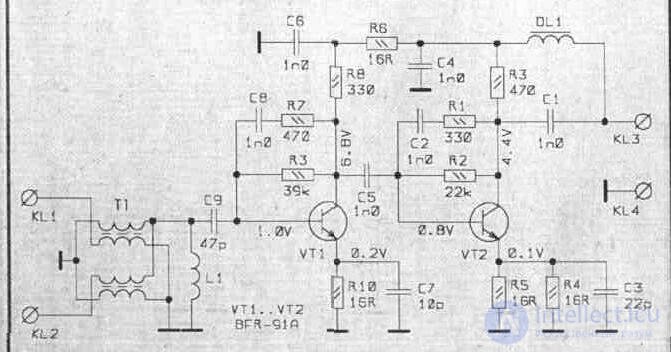
ANPREL WS-2
Reception channels 1 - 68
Gain (G), dB 23 ... 26
Noise ratio (F), dB 3, 1
Input / output resistance, Ohm 300/75
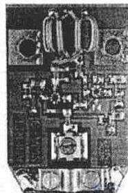
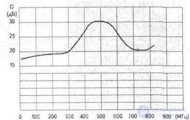
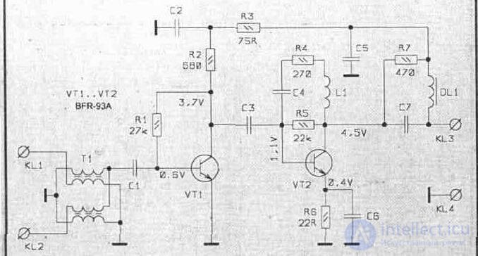
SWA-3
Reception channels 1 - 68
Gain (G), dB 23 ... 28
Noise ratio (F), dB 3, 1
Input / output resistance, Ohm 300/75
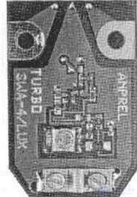
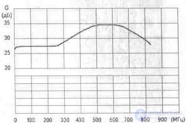
SWA-4 LUX
Reception channels 1 - 68
Gain (G), dB 28 ... 32
Noise ratio (F), dB 2, 6
Input / output resistance, Ohm 300/75
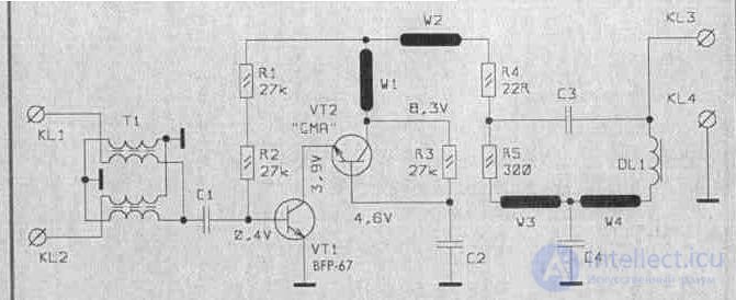
SWA-5 (SWA-6)
Reception channels 1 - 68
Gain (G), dB 32 ... 36
Noise ratio (F), dB 1, 9
Input / output resistance, Ohm 300/75
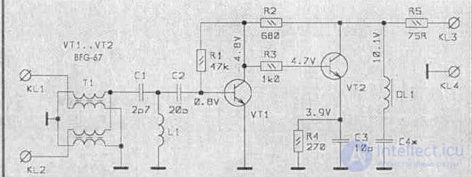
SWA-7
Reception channels 1 - 68
Gain (G), dB 32 ... 38
Noise ratio (F), dB 1, 7
Input / Output Resistance Ohm 300/75
SWA-8
Reception channels 1 - 68
Gain (G), dB 28 ... 30
Noise ratio (F), dB 2, 9
Input / output resistance, Ohm 300/75
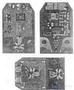
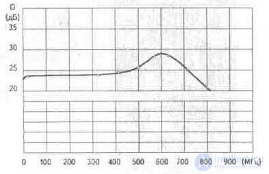
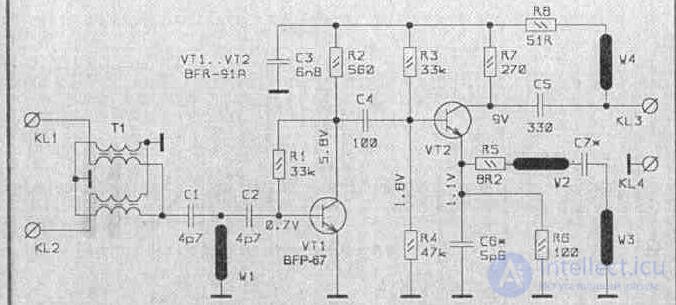
SWA-9
Reception channels 1 - 68
Gain (G), dB 32 ... 39
Noise ratio (F), dB 1, 7
Input / Output Resistance Ohm 300/75
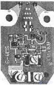
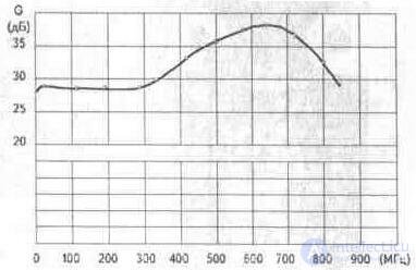
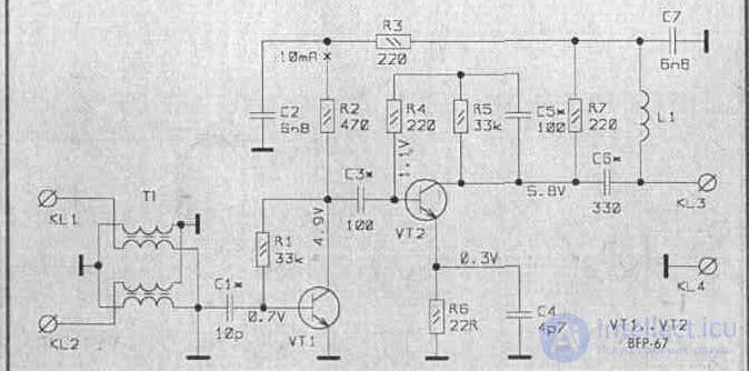
SWA-455 LUX
Reception channels 1 - 69
Gain (G), dB 22 ... 30
Noise ratio (F), dB 1, 8
Input / output resistance, Ohm 300/75
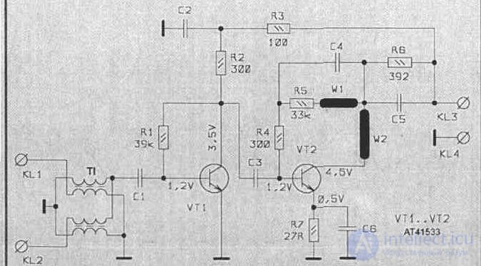
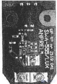
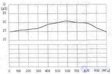
SWA-555 LUX
Reception channels 1 - 69
Gain (G), dB 28 ... 34
Noise ratio (F), dB 1, 7
Input / output resistance, Ohm 300/75
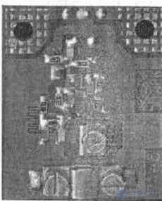
PA-5
Reception channels 1 - 69
Gain (G), dB 28 ... 34
Noise ratio (F), dB 1, 7
Input / output resistance, Ohm 300/75
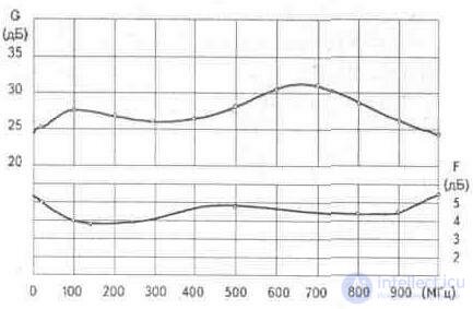
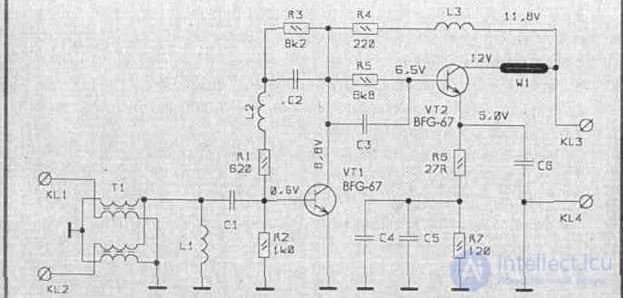
S & A-130
Reception channels 1 - 69
Gain (G), dB 28 ... 34
Noise ratio (F), dB 1, 7
Input / output resistance, Ohm 300/75
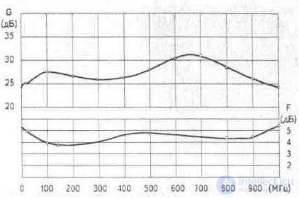
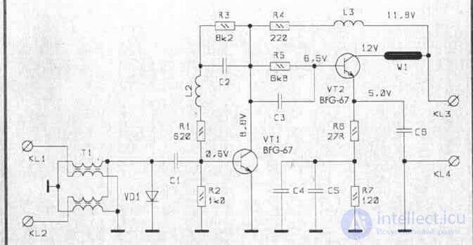
PA-9
Reception channels 1 - 69
Gain (G), dB 28 ... 34
Noise ratio (F), dB 1, 7
Input / output resistance, Ohm 300/75
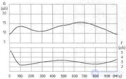
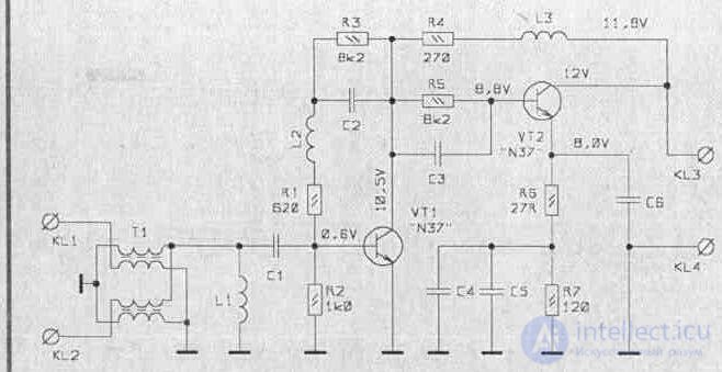
S & A-140
Receive channels, 1 - 69
Gain (G), dB 28 ... 34
Noise ratio (F), dB 1, 7
Input / Output Resistance Ohm 300/75
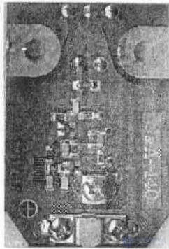
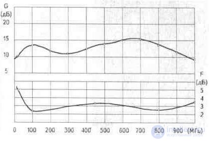
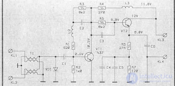
RA-10
Receive band, MHz 40 ... 800
Gain (G), dB 22
Noise ratio (F), dB 3, 9
Input / output resistance, Ohm 300/75
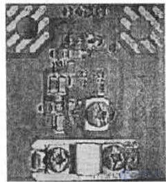
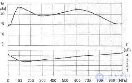
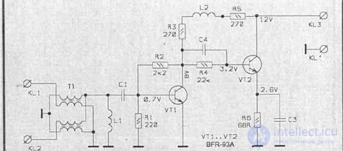
S & A-120
Receive band, MHz 40 ... 800
Gain (G), dB 22
Noise ratio (F), dB 3, 9
Input / output resistance, Ohm 300/75
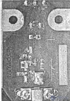
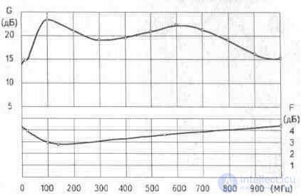
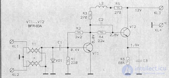
RAE-14
Reception channels 1 - 60
Gain (G), dB 25 ... 30
Maximum output level (P), dB / µV 98
Noise ratio (F), dB 1, 5
Input / output resistance, Ohm 300/75
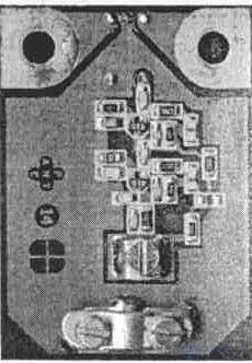
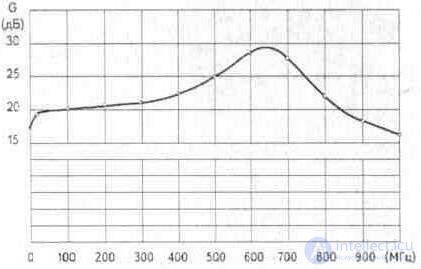
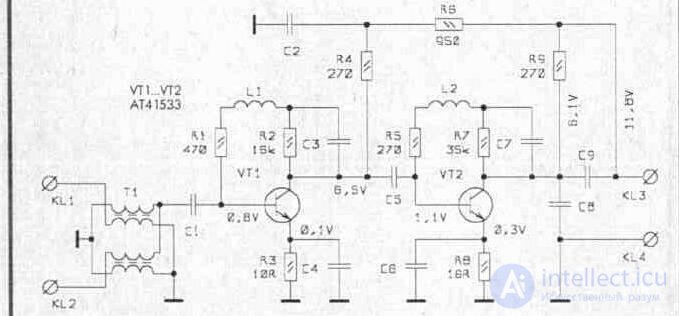
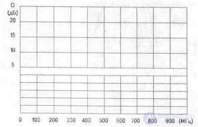
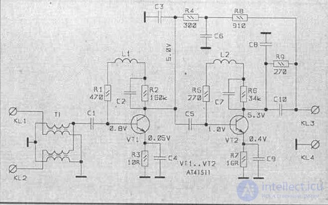
RAE-42
Reception channels 1 - 60
Gain (G), dB 25 ... 30 * Noise (F), dB <2.5 (UHF) Maximum output level (P), dB / µV 102
SWR 1, 8
Output resistance, Ohm 75
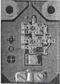
RAE-43
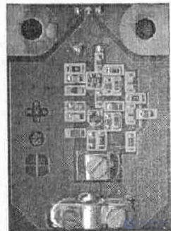
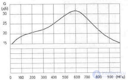
Reception channels 1 - 69
Gain (G), dB 26 ... 32 Noise (F), dB <2.5 (UHF) Maximum output level (P), dB / µV 104
SWR 1, 2
Output resistance, Ohm 75
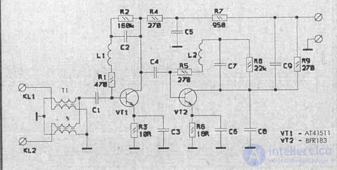
RAE-44
Reception channels 1 - 60
Gain (G), dB 26 ... 32 Noise (F), dB <2.7 (UHF) Maximum output level (P), dB / µV 98
KSV 1, 5
Output resistance, Ohm 75
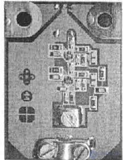
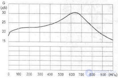
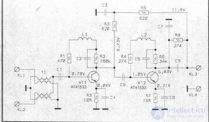
RAE-45
Reception channels 1 - 69
Gain (G), dB 24 ... 28
Noise ratio (F), dB <2.2 (UHF) Maximum output level (P), dB / µV 105
SWR 1, 2
Output resistance, Ohm 75
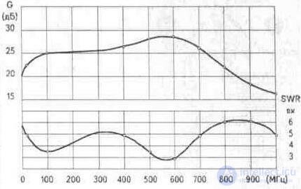
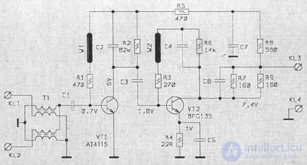
RAE-65
Reception channels 1 - 69
Gain (G), dB 24 ... 28 Noise (F), dB <2, 5 (UHF) Maximum output level (P), dB / µV 104
SWR 1, 2
Output resistance, Ohm 75
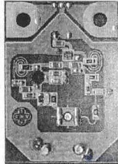
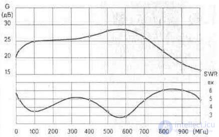
RAE-65 TS
Reception channels 1 - 69
Gain (G), dB 24 ... 28 Noise ratio (F), dB <1.7 (UHF) Maximum output level (P), dB / µV 112
SWR 1, 7
Output resistance, Ohm 75
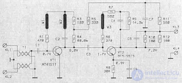
GPS WA-031
Receive channels 6-60
Gain (G), dB 22
Noise ratio (F), dB 3, 0
Input / output resistance, Ohm 300/75
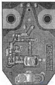
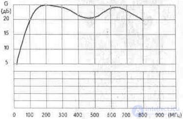
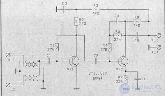
GPS WA-032
Receive channels 6 - 60
Gain (G), dB 24
Noise ratio (F), dB 2, 2
Input / output resistance, Ohm 300/75
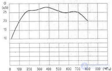
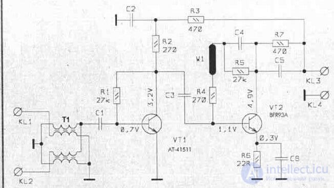
GPS WA-041
Receive channels 6-60
Gain (G), dB 32
Noise ratio (F), dB 1, 7
Input / output resistance, Ohm 300/75
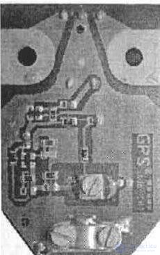
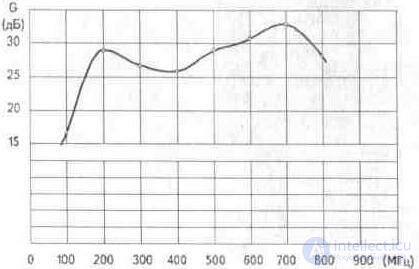
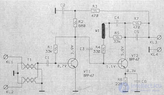
GPSWA-042
Receive Channels 6-60
Gain (G), dB 32
Noise ratio (F), dB 1.7
Input / output resistance, Ohm 300/75
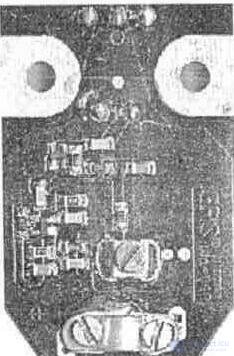
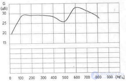
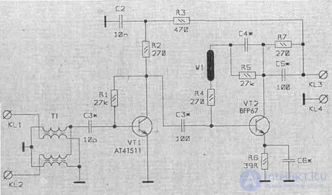
GPS WA-501S-1 (3)
Receive channels 6 - 60
Gain (G), dB 32
Noise ratio (F), dB 1, 5 .. 1, 6
Input / output resistance, Ohm 300/75
Comments
To leave a comment
Television and antennas. Theory. Broadcast and cable. Digital and analog
Terms: Television and antennas. Theory. Broadcast and cable. Digital and analog