Lecture
The subject, content and objectives of the study of the discipline.
Basic concepts and definitions. Reliability; renouncement; failure rates; maintainability; durability; survivability. Reliability of electro-radio elements. Reliability in parallel and serial block connection
Maintenance of electronic equipment.
Types (classification) of reservation.
Redundancy as ensuring the required level of reliability
Reliability is the ability of a product to perform specified functions over a period of time. Each deviation from the set parameters is a malfunction. In the event of a loss of functionality, a failure occurs .
Types and causes of failures
There are three types of failures:
1. Failures due to latent manufacturing defects;
2. Failures due to random factors;
3. failure due to aging and wear.
Maintainability
maintainability is one of the main properties of reliability (See Reliability); consists in the adaptability of the product (technical devices) to carry out various works on its maintenance (see. Maintenance) and repair. Repair is determined by the operational and repair manufacturability of the product. Operational manufacturability - adaptability to work performed during maintenance, as well as in preparing the product for operation, in the process and at the end of it. Repair manufacturability - adaptability to quick, convenient repair. In a narrower sense, Repair refers to the adaptability of the device to the convenient and quick implementation of individual technological operations during its maintenance, repair, monitoring of the technical condition, during disassembly (assembly) of units and parts of the device, their monitoring and replacement. Repair is provided during the design and manufacture of the product - the right choice of design and compliance with production technology.Maintenance of the Repair during the operation of the product is achieved by a rational system of maintenance and repair. Repair is characterized by the average recovery time and the probability of recovery during a certain time interval, Availability by coefficient, Technical use by coefficient, Interchangeability, Degree of unification etc.
DURABILITY - the property of a technical object to maintain (subject to maintenance and repairs) a healthy state for a certain time or up to a certain amount of work. Durability is characterized by a technical resource or service life.
Survivability - the ability of a technical device, structure, means or system to perform its main functions, despite the damage received, or adapting to new conditions
To quantitatively characteristics of reliability
The distribution function F (t) of failures or the error function — this characteristic is obtained during a durability test when the failure of elements is noted at certain intervals of time, it always increases monotonically and changes from 0 to 1 at the beginning and end of the durability period, respectively. If the probability that the element will function by time t, F (t), then the probability of failure-free operation is
R (t) = 1-F (t).
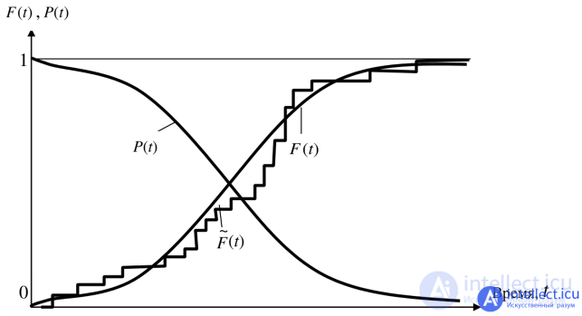
Fig. An approximate form of the distribution function F (t ) and the reliability function P (t )
Failure probability density
f (t) = dF (t) / dt is the probability that the element will fail within the time interval t- (t + dt).
The most essential for practice is the failure rate - this is the change in the number of functioning elements per unit of time, referred to as elements that are operational at this time
λ (t) = f (t) / R (t).
The average uptime is determined by the average life of individual batch elements with integration from 0 to ∞
_t = ∫R (t) dt
The period of normal operation is a period of time with a constant failure rate.
Mean time between failures: tav = 1 / λ
Failure rate
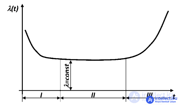
A typical dependence of the failure rate on time: I - the period of running-in and failures of low-quality products; II - the period of normal operation; III - aging period (failures are caused by wear of parts or aging of materials). The failure rate of some products (for example, semiconductor devices) does not increase over the entire period of operation, that is, it does not have an aging period, therefore, it is sometimes said that their service life is eternal.
Failure rate - the ratio of the number of failed objects (samples of equipment, products, parts, mechanisms, devices, units, etc.) per unit time to the average number of objects that are working properly in a given period of time, provided that the failed objects are not restored and do not replaced by serviceable. In other words, the failure rate is numerically equal to the number of failures per unit time, referred to the number of nodes that have worked flawlessly before that time. The following failure rate definitions are equivalent:
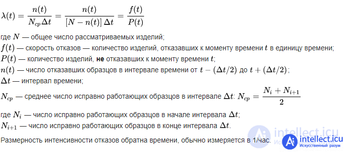
Failure Rate Examples
When testing a duration of 3000 hours out of 1000 products, 150 failed. Then the failure rate of these products:
 1 hour.
For example, average failure rates during normal operation are:
 1 / hour or 0.01 1 / year;
 1 / hour or 0.13 1 / year.
The most statistically reliable failure rate data is collected for electronic components.
 1 / hour.
 1 / hour.
 1 / hour.
 1 / hour.
 1 / hour.
Instrument reliability
The failure rate of a device consisting of K types of structural elements is
λpr = Σnkλec
Therefore, when designing, elements with the lowest failure rate are selected and it is also inexpedient to choose expensive elements with a small number of them in the device.
To calculate the reliability parameters, it is convenient to use the structural - logical schemes of the reliability of the TS, which graphically display the relationship of the elements and their influence on the performance of the system as a whole. Structural - logical scheme is a set of previously selected elements connected to each other in series or in parallel. The criterion for determining the type of connection of elements (serial or parallel) when constructing a circuit is the effect of their failure on the performance of the vehicle.
A connection (in terms of reliability) is considered a connection in which a failure of any element leads to a failure of the entire system (Fig. 2.1).
A connection is considered parallel (from the point of view of reliability), in which a failure of any element does not lead to a failure of the system until all connected elements fail (Fig. 2.2).

fig. 2.1
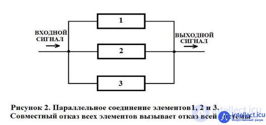
fig. 2.2
Not always the type of connection of the elements of the system in the structural diagram of reliability coincides with the actual electrical or mechanical type of connection of the elements in the system. Therefore, the structural diagram of reliability may differ from the structural diagram of the actual connection of the elements.
It should be clarified that such a connection of elements is "sequential" only in the sense of reliability, physically they can be connected as you like.
From the standpoint of reliability, such a connection means that the failure of the device consisting of these elements occurs when the failure of element 1, or element 2, or element 3, or element n . The condition for operability can be formulated as follows: the device is operable if element 1 is operational, and element 2, and element 3, and element n .
We express the reliability of this system through the reliability of its elements. Suppose there is a certain period of time (0, τ) during which it is required to ensure the failure-free operation of the system. Then, if the reliability of the system is characterized by the law of reliability P ( t ), it is important for us to know the value of this reliability at t = τ, i.e., P (τ). This is not a function, but a certain number; discard the argument τ and denote the reliability of the system simply P . We similarly denote the reliability of individual elements P 1, P 2, P 3, ..., P n.
For the failure-free operation of a simple system during the time τ, it is necessary that each of its elements operate without fail. This is evidenced by the site https://intellect.icu. Let us denote S - an event consisting in the failure-free operation of the system in time; s 1, s 2, s 3, ..., s n are events consisting in the failure-free operation of the corresponding elements. Event S is the product (combination) of events s 1, s 2, s 3, ..., s n:

Suppose that the elements s 1, s 2, s 3, ..., s n fail independently of each other (or, as they say with respect to reliability, they are “independent of failures”, and very briefly: “independent”). Then, according to the rule of multiplication of probabilities for independent events, P ( S ) = P ( s 1) ⋅ P ( s 2) ⋅ P ( s 3) ⋅ ... ⋅ P ( sn ) or in other notations:

and in short:

that is, the reliability (the probability of a healthy state) of a simple system composed of independent in failures, series-connected elements is equal to the product of the reliability of its elements.
In the particular case, when all the elements have the same reliability P 1 = P 2 = P 3 = ... = Pn , expression (4.5.2) takes the form:

EXAMPLE 4.5.1. The system consists of 10 independent elements, the reliability of each of which is equal to P = 0.95. Determine the reliability of the system.
By the formula (4.5.3), P = 0.9510 ≈ 0.6.
The example shows how sharply the reliability of the system decreases with an increase in the number of elements in it. If the number of elements n is large, then to ensure at least an acceptable reliability P of the system, each element must have very high reliability.
We pose the question: what reliability P must an individual element have in order for a system composed of n such elements to have a given reliability P ?
From the formula (4.5.3) we get:

In fig. 4.5.6 shows a parallel connection of elements 1, 2, 3. This means that the device consisting of these elements goes into a failure state after the failure of all elements, provided that all elements of the system are under load and the failures of the elements are statistically independent.
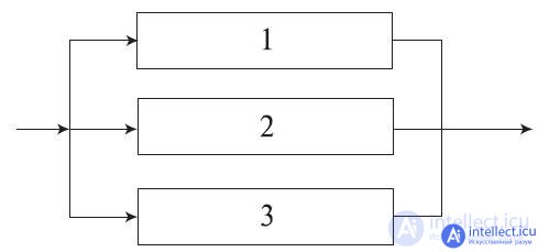
Fig. 4.5.6. Block diagram of a system with parallel connection of elements.
The condition for operability of the device can be formulated as follows: the device is operable if element 1, or element 2, or element 3, or elements 1 and 2, 1 and 3, 2 and 3, 1 and 2 and 3 are operational.
The probability of a failure-free state of a device consisting of n parallel-connected elements is determined by the probability addition theorem of joint random events as

For the given block diagram (Fig. 4.5.6), consisting of three elements, expression (4.5.8) can be written:

In relation to reliability problems, according to the rule of multiplying the probabilities of independent (in aggregate) events, the reliability of a device of n elements is calculated by the formula:

i.e., in a parallel connection of independent (in the sense of reliability)  elements of their unreliability (1 - pi = qi ) are multiplied. In the particular case, when the reliability of all elements are the same, formula (4.5.9) takes the form:

EXAMPLE 4.5.5. The safety device, which ensures the safety of the system under pressure, consists of three valves duplicating each other. The reliability of each of them is p = 0.9. Valves are independent in terms of reliability. Find device reliability. Decision. By the formula (4.5.10)
P = 1 - (1 - 0.9) 3 = 0.999.
The failure rate of a device consisting of n parallel-connected elements with a constant failure rate λ0 is defined as:

From (4.5.11) it can be seen that the failure rate of the device for n > 1 depends on t : at t = 0 it is equal to zero, with increasing t , it monotonically increases to λ0.
If the failure rates of the elements are constant and subject to the exponential distribution law, then expression (4.5.9) can be written:

We find the average system uptime T 0 by integrating equation (4.5.12) in the interval [0, ∞]:

In the case when the failure rates of all elements are the same, expression (4.5.13) takes the form:

The mean time to failure can also be obtained by integrating equation (4.5.8) in the interval [0, ∞].
EXAMPLE 4.5.6. Suppose that two identical fans in an exhaust gas purification system work in parallel, and if one of them fails, the other is able to operate at full system load without changing its reliability characteristics.
It is required to find the system failure-free operation within 400 hours (duration of the task), provided that the failure rates of the fan motors are constant and equal to λ = 0.0005 h – 1, the engine failures are statistically independent and both fans start to work at time t = 0.
Decision. In the case of identical elements, the formula (4.5.12) takes the form:
P ( t ) = 2exp (−λ t ) - exp (−2λ t ).
Since λ = 0.0005 h-1 and t = 400 h, then:
P (400) = 2exp (−0,0005 × 400) - exp (−2 × 0,0005 × 400) = 0.9671.
We find the mean time between failures using (4.5.13):
T 0 = 1 / λ (1/1 + 1/2) = 1 / λ × 3/2 = 1.5 / 0.0005 = 3000 h.
Industrial reliability is the ratio of the number of operations performed flawlessly on tuned equipment to the total number of operations performed.
Improving reliability. Methods of increasing reliability in design and.
Improving reliability can be achieved in two ways:
1-by underloading the elements,
2-way redundancy.
In the first case, the service life increases due to a decrease in the aging period.
In the second case, when redundant, they create redundancy of functional elements that replace a failed element.
Determination of the optimum operating point
Functional blocks fail not only due to manufacturing errors, sudden failures, but also due to the coincidence of many factors affecting their functioning. When designing the device, they try to take this into account to achieve a high degree of reliability.
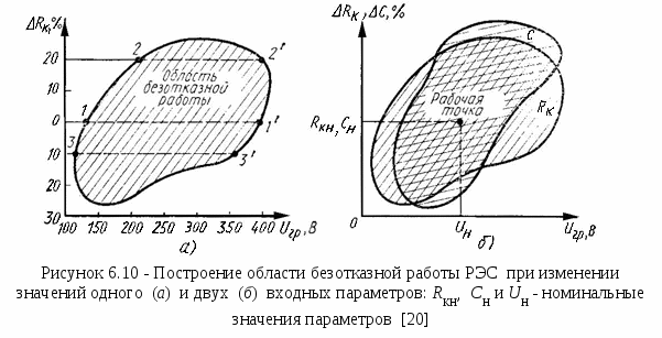
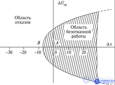
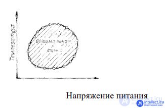
RIS Boundary Test Schedule
To assess it during operation, the dependence of individual parameters on each other is presented, at which failures occur. For this purpose, parameters not involved in the study are set to nominal values, but only two parameters vary, for example, voltage and temperature.
Many combinations of these parameters are determined at which the product ceases to function. When graphically presenting the results, a graph of boundary values is obtained (Fig.). Inside the area, the functioning of the unit is guaranteed, outside - failure.
The optimal parameter point lies at the center of this area.
During the operation of elements and systems, failures must be eliminated, as well as the possibility of their occurrence being prevented. These measures include making adjustments and replacing devices that are still operational (depending on their operating time, deviation of parameters from the nominal or any other signs of aging and wear). The proper organization, timely, complete and high-quality implementation of these measures to a large extent determine the reliability of elements and systems in operating conditions. Of particular importance are preventive measures. It is known that in order to ensure the specified reliability of the developed equipment, designers have the opportunity to provide for the scope of preventive measures and the timing of their implementation.Failure to perform these measures or increase the interval between them inevitably leads to a decrease in the reliability of elements and systems.
Under operating conditions, the implementation of the process schedule is of great importance when all routine maintenance is carried out in a timely manner and in a volume that ensures that the reliability of elements and systems is maintained within specified limits. In this case, of course, control over the implementation of the process by managers is important.
Redundancy is the use of backup means of ensuring the health of an object. Depending on the type of backup funds used, redundancy happens: functional, temporary, informational, structural.
Functional reservation is a reservation in which the ability of elements to perform additional functions is used, as well as the ability to perform a given function by additional means.
Such redundancy is often used for multifunctional systems in which the values of the same process state parameters can be obtained using different devices and based on different calculations.
Temporary reservation is a reservation in which reserve time is used to perform a given function.
Temporary backup is that interruption in the functioning of a system or device due to a failure of an element is allowed. For example, to transmit information of a given volume, time t is required . When planning work for this operation, the time t + tp is allocated, where tp is the standby time. Standby time can be used either to repeat the transmission of information, or to eliminate hardware malfunctions. The introduction of standby time improves the reliability of the facility, but at the same time reduces the productivity of its work.
Information reservation is a reservation in which excess reserve information is used as a reserve. This type of reservation includes the introduction of redundant information symbols during the transmission, processing and display of information, for example, the use of additional bits in the encoding of information. This allows you to detect and even eliminate errors in the transmission of information (corrective codes).
Structural redundancy is a reservation using redundant elements of the structure of an object.
This type of redundancy is the most common and most effective means of increasing reliability because the physical meaning of it is most understandable to the developer and this method is more accessible than others for implementation. If the developer doubts the reliability of some element of the structure of the object, he additionally introduces a backup element into the structure. The same element can be used as a spare, but replacing a failed element with a spare one causes big time losses and is often technically impossible during operation. The inclusion of backup elements in the structure is a kind of automation of the process of replacing a failed element.
With structural redundancy, all elements of the system can be divided into primary and backup.
The main element of the structure is the element that performs the specified functions.
A fallback member is an element designed to replace a core member.
Not every primary element may have a backup element permanently connected. For example, constantly connecting a backup battery to the main battery changes the performance of the power system. The inclusion of a backup computer in the structure is associated with solving a number of complex technical problems, for example, synchronizing the operation of a computer, continuous monitoring of the technical condition of the system, ensuring the reliability of switching devices, etc. Therefore, there are several methods of structural redundancy for specific operating conditions of an object.
Structural redundancy is divided into general and separate.
In general, the system is reserved as a whole, while separate, individual elements or their groups are reserved.

If the backup elements operate on a par with the basic, then there is a constant backup or passive. If the reserve is introduced into the system after the failure of the main element and is accompanied by switching operations, then there is a replacement reservation or an active reservation.
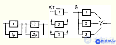
When redundant by redundancy, redundant elements may be in a loaded, light or unloaded state. If the backup item is in the same mode as the primary item, then the backup is called loaded or hot backup; if the backup element is in less loaded mode than the main, the backup is called lightweight or warm redundancy; if the backup element is not carrying a load, the backup is called unloaded or cold backup.
When reserving by replacement, the same reserve can be used to replace any of a number of elements of the same type. This backup method is called rolling.
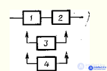
When calculating reliability, it is assumed that the backup elements are always ready for immediate connection to work as soon as a command to connect them is received. If such an assumption cannot be made, either a real or a fictitious device for switching to the reserve with its characteristics (reliability, delay time) is introduced into the calculation scheme.
In information systems, dynamic redundancy is used - this is redundancy with the restructuring of the structure of an object when a failure of its element occurs. In fig. the main data path is indicated by a solid line, the possible paths by a dashed line.
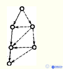
Structural redundancy is used not only to increase the reliability of the product, but also to increase the reliability of the values at its output. For example, in order to increase the reliability of the result of the work of a computer, two machines solve the same problem. The result is considered true if the results of two machines match. This “redundancy” is called duplication.
The combination of working elements can be more complicated than with duplication. For example, the number of running machines may be three. A result is considered true if it matches the results of at least two cars. Such a “reservation” is called a majority reservation or a “voting” reservation. In this case, it will be called majority reservation on the principle of "two out of three."
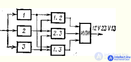
To characterize the relationship between the number of redundant and basic elements, the concept of redundancy ratio k is introduced.
The value of k is an integer when booking with integer multiplicity, when the number of basic elements is equal to one. The value of k is a fractional number when reserving with fractional multiplicity, when the number of basic elements is more than one. In this case, the fraction cannot be reduced.

One of the main means of ensuring the required level of reliability and, above all, the reliability of an object or ES with insufficiently reliable elements is redundancy. By redundancy is meant the use of additional tools and capabilities in order to maintain the operational state of the electric power supply in case of failure of one or more of its elements. Redundancy is an effective way to create ES, the reliability of which is higher than the reliability of the elements included in this system.
During redundancy, the main structural elements are distinguished, which are necessary for the system to perform the required functions in the absence of failures of its elements, and the redundant elements intended to perform the functions of the main elements in case of failure. The ratio of the number n p of backup elements of the system to the number n 0 of the basic elements reserved by them, expressed by an unabridged fraction, is called the multiplicity of the reserve: mp = np / n0
A reservation with a reserve ratio of mp = 1/1 is called duplication.
Additional tools and capabilities used in redundancy include elements that are introduced into the ES structure as reserve ones; the use of functional and information tools and capabilities; the use of excess time and reserves of load capacity. Accordingly, the following types of redundancy are distinguished by the type of additional funds (Fig. 1): structural (using redundant elements of the object's structure); functional (using functional reserves); informational (reserves of information are used); load (using load reserves).
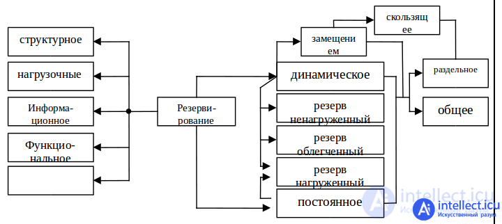
Fig. 1. Classification scheme of types of redundancy.
according to the method of switching on the reserve , there are distinguished between constant and dynamic redundancy : constant is performed without restructuring the system structure when a failure of its element occurs, and dynamic redundancy is performed with a restructuring of the system structure when a failure of its element occurs. In the simplest case, with constant redundancy, parallel connection of elements without switching devices is performed, and with dynamic redundancy, switching devices that respond to element failure are required.
Dynamic backup is often a replacement backup, in which the functions of the main element are transferred to the backup only after the failure of the main element. A common type of redundancy redundancy is rolling redundancy, in which a group of the main elements of the system is reserved by one or more redundant elements, each of which can replace any failed main element in this group.
the operating mode of the backup elements to failure of the main element distinguish the loaded reserve (one or more backup elements are in the main element mode); lightweight reserve (one or several backup elements are in less loaded mode than the main element); unloaded reserve (one or several backup elements are in loaded mode until they begin to perform the functions of the main element).
The concepts of loaded, lightweight and unloaded reserve are used to distinguish reserve elements in terms of their reliability. The elements of the loaded reserve have the same level of reliability (reliability, durability and retention) as the main element objects reserved by them, since the course of the reserve elements is consumed as well as the main elements. The lightweight reserve elements have a higher level of reliability, since the resource consumption rate of the backup elements until the moment they are turned on instead of the failed ones is much lower than that of the main ones. With an unloaded reserve, the resource of the backup elements begins to be consumed almost only from the moment they are switched on instead of the failed elements.
by the method of replacing the object (element of the object) distinguish between general and separate reservation ; when the object as a whole is generally reserved, that is, instead of one object, it is provided for the simultaneous operation of two or more objects of the same type or similar in function (the method is simple and widely used in practice when backing up the most critical systems); in case of separate reservation, individual elements of an object or their group are reserved (separate reservation is usually built-in to an object, i.e., both individual elements of the system and quite large parts of it can be separately reserved).
Dynamic redundancy can be separate and general and allows you to use redundant elements not only in the loaded, but also in lightweight and unloaded reserve, which allows you to save the resource of the backup elements, increase the reliability of the power supply as a whole and reduce energy consumption. The disadvantages of dynamic redundancy by replacement include the need for switching devices and the presence of interruptions in the transition to the backup elements.
Comments
To leave a comment
Reliability of electronic devices
Terms: Reliability of electronic devices