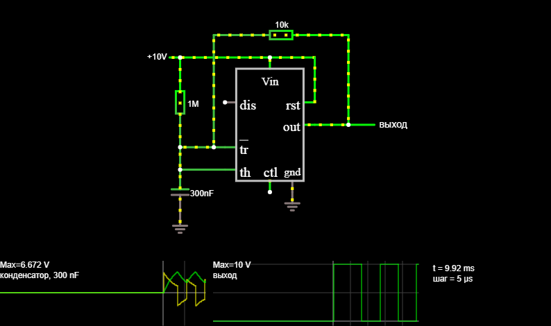
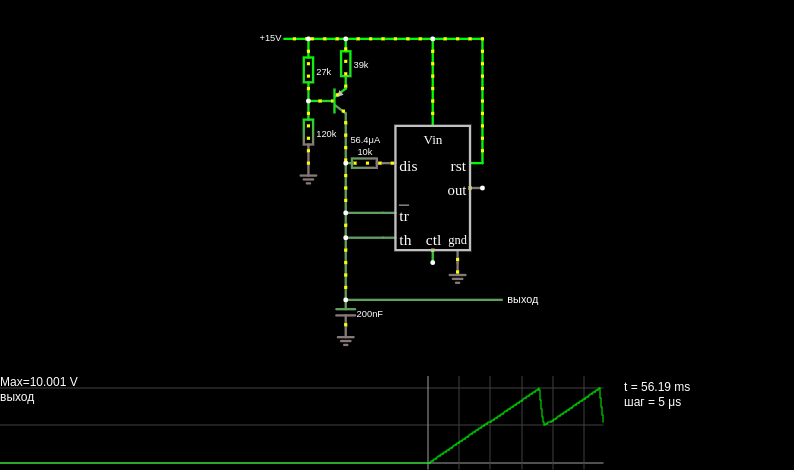
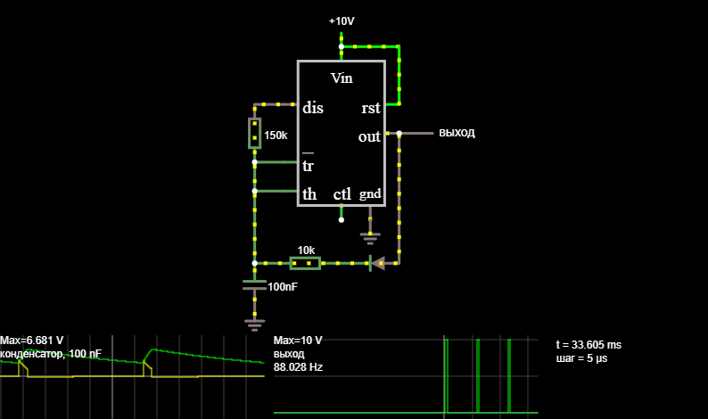
Shown here are the (simplified) internals of the 555 timer chip. As in the last example, this is a square wave. A voltage divider sets the inputs of two op-amps (used as comparators). The upper op-amp compares the trigger input with 1/3 of the supply voltage. The lower op-amp compares the threshold input with 2/3 of the supply voltage. The timing interval begins when the trigger input becomes low enough to trip the upper op-amp. This sets the flip-flop, causing the output to go high. The 555 waits for the threshold input to trip the lower op-amp. As the capacitor charges, the threshold input slowly rises until it reaches the required level. Then the op-amp resets the flip-flop, pulling the output low. The inverted flip-flop output also supplies current to the base of the transistor at the bottom, which discharges the capacitor through the discharge input. When the capacitor is discharged enough to trip the upper op-amp again, a new timing interval begins.
This page is a utility for simulating internal structure online with specified initial values.


Comments