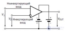
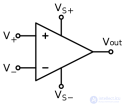
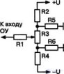
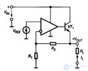
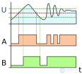
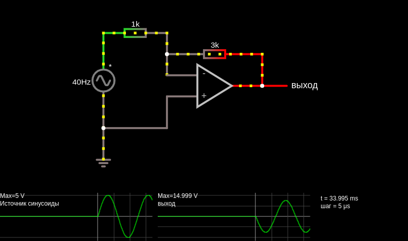
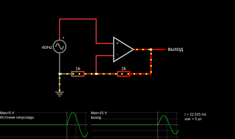
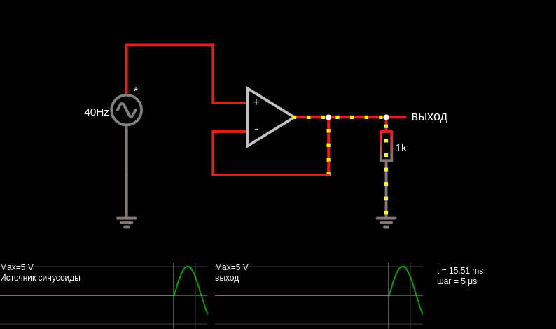
This circuit is a Schmitt trigger, a type of comparator. It measures the input to see whether it is above or below a certain threshold. The threshold changes to reduce the likelihood of the output switching back and forth rapidly due to a noisy input near the threshold. The input signal is a noisy 40 Hz sine wave, shown on the first scope. The threshold is shown in the second area. The third area is a graph of output versus input. Note that the threshold is lowered whenever the input signal exceeds it, and vice versa. Two 10 kΩ resistors form a voltage divider that sets the threshold voltage (the op-amp's + input) at 5 V. But the op-amp's output is also connected to the threshold input through a 100 kΩ resistor. This causes the threshold to increase or decrease slightly depending on the op-amp's output.
This page is a utility for simulating schmitt trigger (op-amp) online with specified initial values.

Comments